

Computed tomography (CT) is rapidly becoming a first-line diagnostic in many veterinary clinics around the world. It is a great resource with applications in all aspects of veterinary medicine. Higher quality CT studies allows for faster and more accurate diagnoses and better outcomes for patients. Developed initially as a diagnostic tool for human medicine, much of the veterinary training is limited or directed specifically at specialist veterinary radiologists. This article will broadly cover the basics of CT imaging that all nurses, technicians or veterinarians should understand before undertaking any CT study.
Acquisition factors
CT images are captured by a series of detectors that move in tandem with a generator in a circle around the patient. The patient lies on the table or couch as it moves through the gantry (Garnett, 2020). Modern CT machines are designed with slip rings to allow continuous spinning of the x-ray source and detector array as the anatomy moves through the field of view (Figure 1).
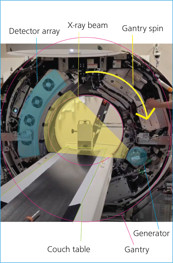
Information is acquired in a spiralling pattern around the patient, which when processed by the computers, can be visualised as three-dimensional (3D) information.
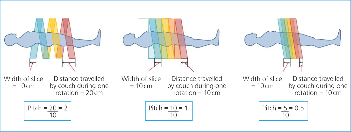
Kilovoltage (kV), milliamperage (mA), field of view and slice thickness are all factors that can be adjusted for best image quality. As with plain film radiography, the user is encouraged to keep the kV and mA as low as reasonable to reduce patient dose. The pitch is the factor that determines the ‘tightness’ of this information spiral. It is a measure of the speed of the table per rotation of the generator (Figure 2). The higher the pitch, the faster the table, and there is less overlap of slices meaning lower detail scans, but a lower dose to the patient. The reverse is also true; the slower the table, the lower the pitch, meaning the slices overlap more for a higher detail scan, but deliver a larger radiation dose to the patient (Bashir, 2021).
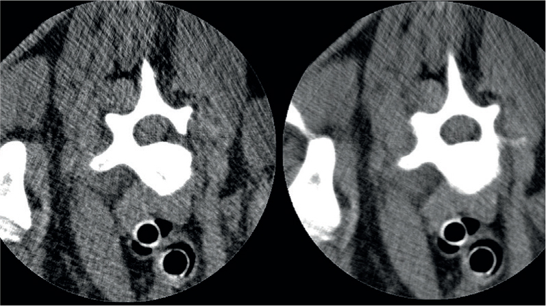
Slice thicknesses can vary based on machine functionality; however, the standard is commonly from 0.5 mm up to 5 mm. The benefit of thin slices is that it reduces the effects of partial volume averaging. As CT is a 3D modality the image is made up of voxels, the 3D equivalent to a two-dimensional pixel. A voxel is a point in space within a 3D matrix (Condon, 2020). When two tissues of significantly different densities are within the same voxel, the beam attenuation is an average of these two densities, accurately representing neither of the tissues. However, thin slices do come with some disadvantages that must be considered. The obvious disadvantage is the increased patient dose. While this is not closely tracked in veterinary patients, it should always be a factor when choosing scan settings. Depending on the size and region to be studied, thinner slices also lead to more images. This may be impractical for reporting purposes, particularly if these large studies are being sent or stored remotely. Studies upwards of 5000 slices can become cumbersome to download and transfer and external services may request that the scan is reformatted into thicker slices for practical purposes. Thin slices may also not be desirable in sections of dense anatomy or through metallic implants as these are at higher risk of beam hardening artefact. The effect of this artefact on your final images may be greatly multiplied by having twice as many slices through the region (Figure 3).
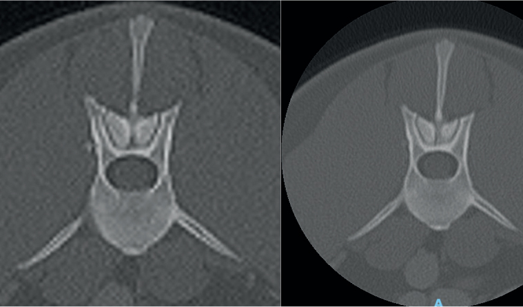
The field of view, often shortened to FOV or ROI (region of interest), is the size of the circle within the gantry that is chosen to scan. Similar to collimation in radiography, the tighter this FOV to the anatomy, the clearer the final image. Each scan has the same number of voxels to allocate to each image produced. A smaller FOV means more voxels to be allocated to the anatomy than if the full field is simply scanned within the gantry and then zoomed in. The effect of this is significant, as can be seen in the comparative images in Figure 4.
Artefacts
Beam hardening is one of the most common CT artefacts. This is seen most often when scanning through very dense objects. As the x-ray beam passes through the object, the lower energy photons are attenuated while the ‘harder’ higher strength photons continue to pass through. This visually creates ‘streaks’ across the image that may obscure pathology (Figure 5). The most effective adjustment that can be made clinically to reduce this artefact is to increase the energy of the x-ray beam. However, high energies may then poorly attenuate through less dense anatomy, providing poor contrast through soft tissues (UTCT, 2020).
Ring artefacts may also be encountered. These artefacts visually appear as a series of concentric rings, like those of a tree trunk. These are caused by miscalibration of the scanner. Air calibrations should be run regularly to prevent these artefacts. It is important to keep the gantry clean and run these calibrations with the gantry clear of all objects including the CT couch. If ring artefacts persist, contact your vendor who will be able to perform a series of calibrations on your machine.
The final artefact that is important to recognise is a tube arc. These are random but relatively common and not of great concern unless happening regularly, in which case they may be an early indicator of equipment failure. Tube arcs are a result of a temporary loss of x-ray output and usually only affect a small handful of slices (Mithun et al, 2016). They are clearly discernible from ring or beam hardening artefacts as these will persist throughout the entire region or be clearly linked to dense anatomy, unlike an arc artefact. Generally, the machine will recognise and advise the practitioner of tube arcs, and newer software will have the ability to digitally repair the image. Where the software is not capable of salvaging the image, it may be necessary to repeat the affected slices.
Positioning
Positioning for CT examinations is less particular than for radiographs, but still requires a level of care. The two major aims of positioning for veterinary CT are to reduce beam hardening artefacts and for post-production reformatting.
As previously discussed, images are most at risk of beam hardening where the FOV contains dense objects or anatomy. Any patient positioning devices such as sandbags should be removed from the FOV for this reason. Radiopaque patient monitoring devices will also cause these artefacts. Plastic tubing such as blood pressure tubing is safe to run through the gantry, but those containing wires such as for electrocardiograms (ECGs) and pulse oximetry need to be out of the scan field for the duration of the scan.
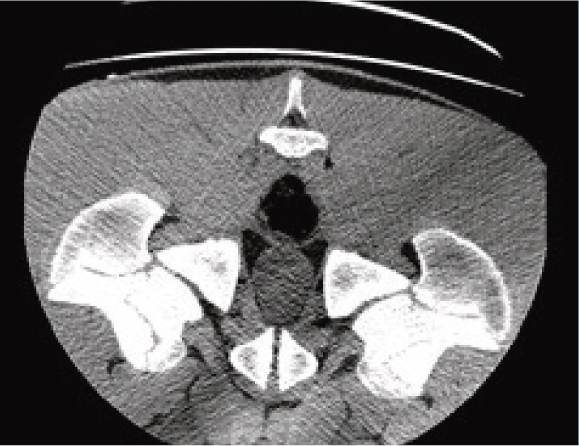
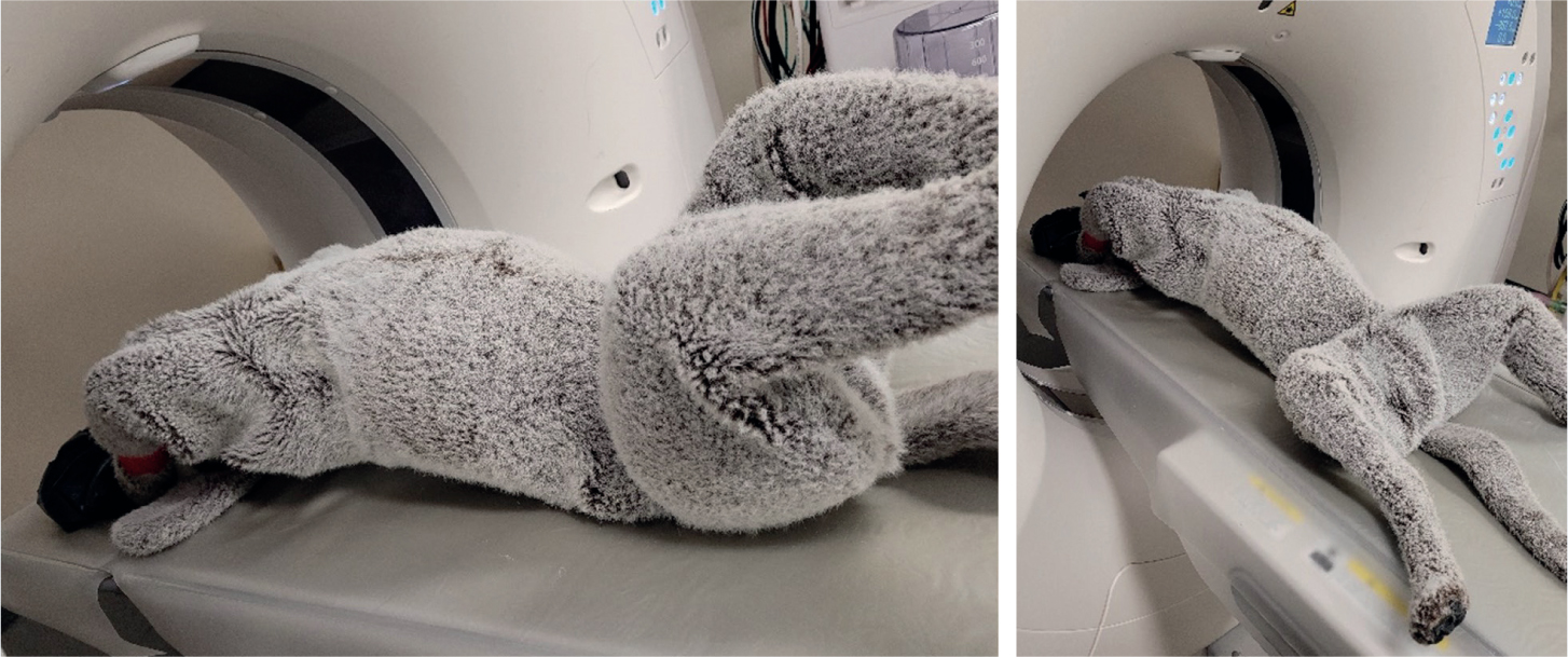
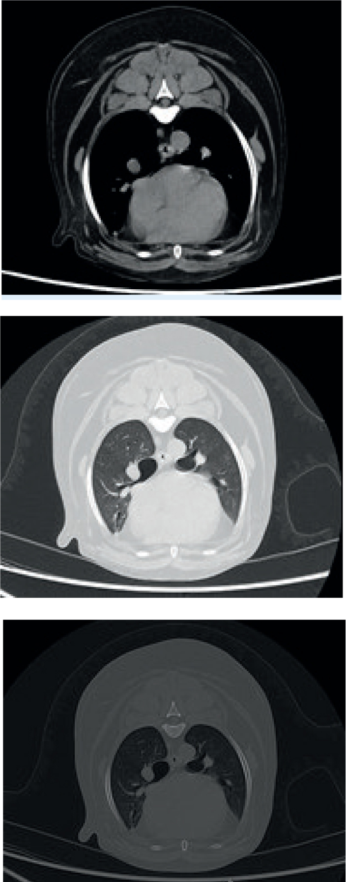
Also avoid anatomy that is not of interest, for example limbs in a trunk study, where possible. When positioning the patient's limbs, it is important to keep long bones perpendicular to the path of the x-ray beam. Significantly more hardening artefact will occur when the beam must travel the length of a long bone vs the width. This is commonly caused by the humeri in the cranial thorax and femurs in caudal abdomen when the limbs are not pulled sufficiently parallel to the couch (Figures 6 and 7).
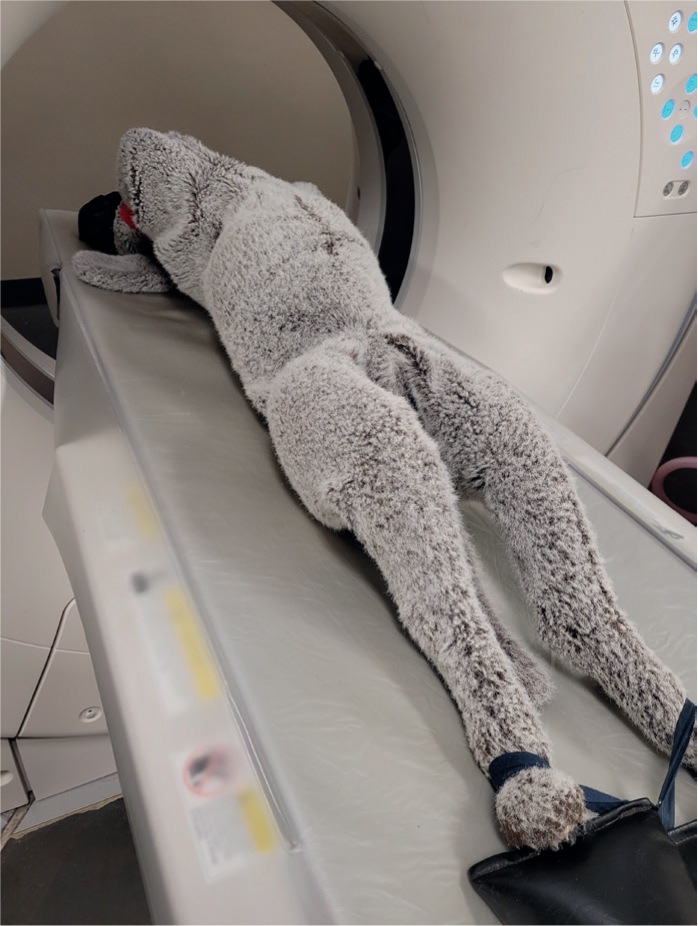
Post-processing, CT images are commonly reformatted into transverse, dorsal and sagittal planes. When scanning, the anatomy of interest should be as close to the isocentre of the gantry as possible for the highest quality image (Figure 8). The horizontal and vertical guidelights of the CT gantry can be used to line up patients. The straighter the patient is for the scan, the easier the images will be to reformat.
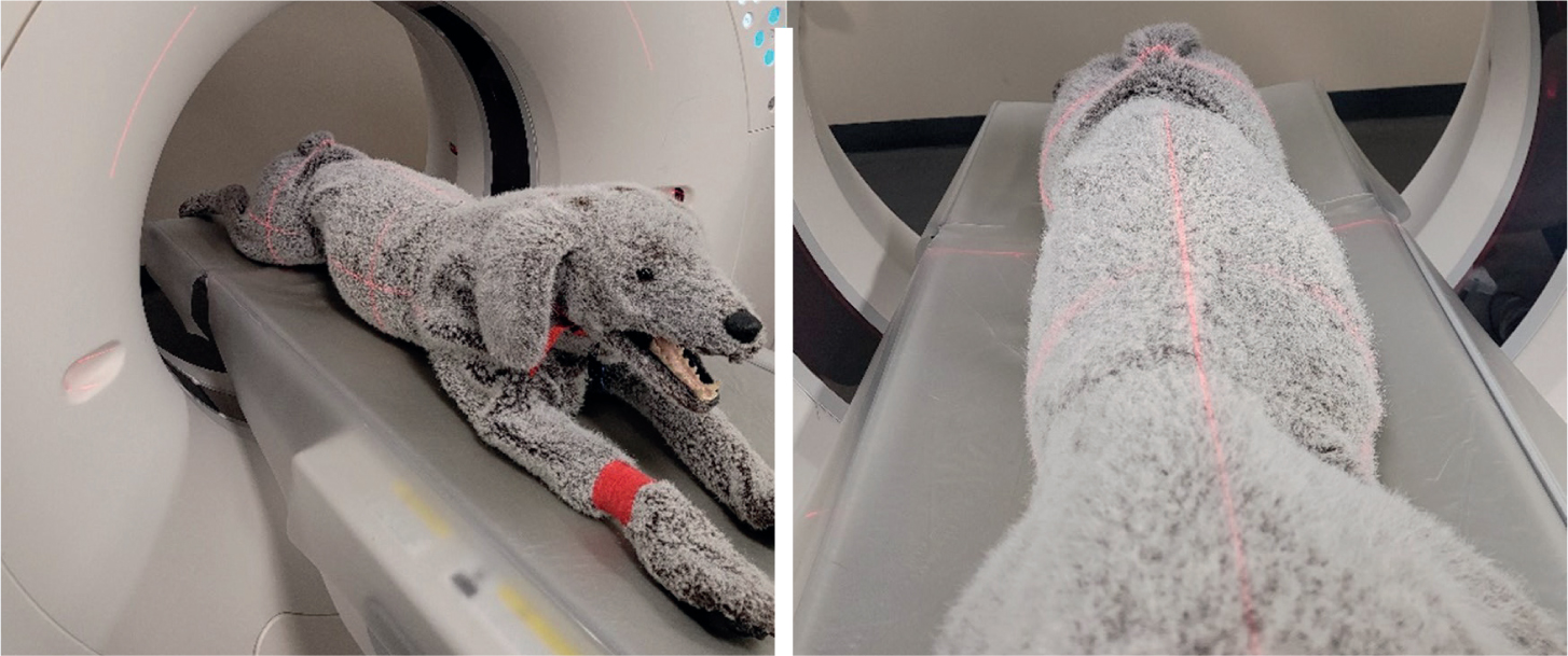
While it is possible to reformat following a curved plane, this is more complicated and subject to user error. Curved plane reconstructions should be reserved for the unavoidable curvature of the spine. When positioning for the spine the patient should be placed in dorsal recumbency. This is the position in which the spine is the straightest and will also reduce the effect of motion caused by respiration.
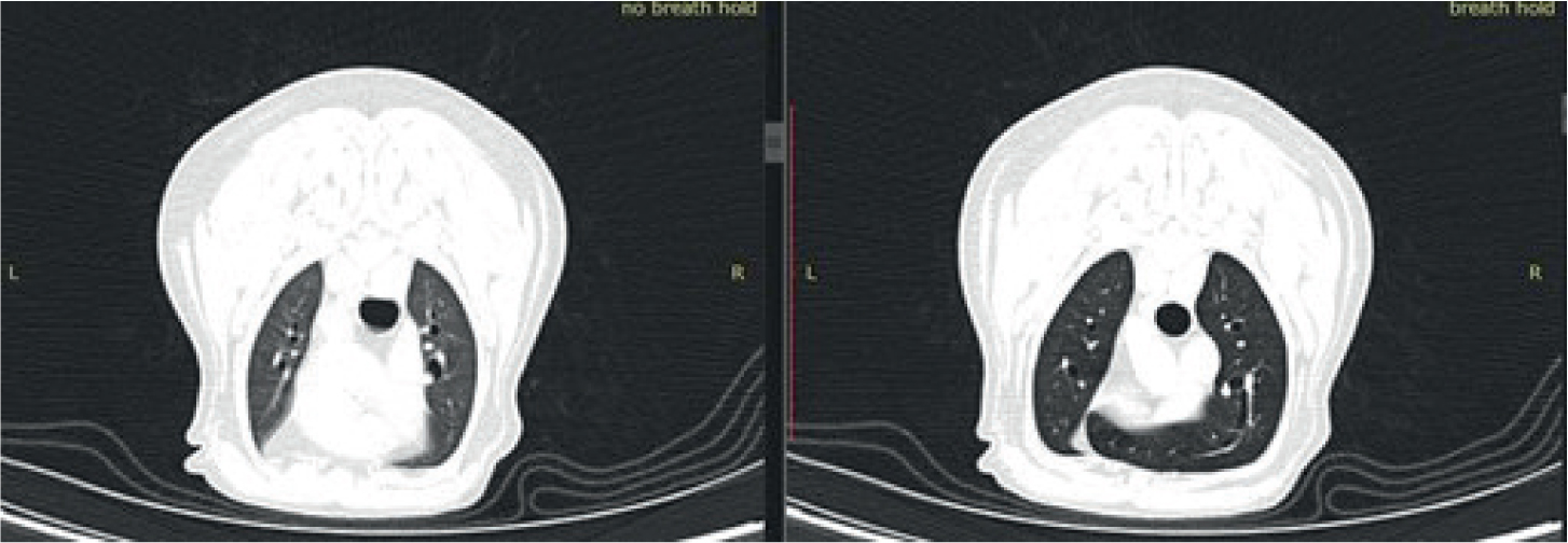
Just like in traditional radiography, motion artefact will significantly degrade the image quality. Patients should be positioned to minimise this effect from breathing where possible. When imaging the thorax or cranial abdomen, a breath hold technique should be used. As veterinary patients cannot simply be asked to hold their breath like patients in human medicine, there are two common breath hold techniques that can be used.
The first and less desirable for chest imaging involves artificially inducing apnoea. This is achieved through pharmaceuticals or a combination of intermittent positive pressure ventilation (IPPV) and capnography. While this does keep the thorax still, thus removing motion artefact, the patient's lungs are not full and inflated.
For best contrast through the lung fields, ideally a long breathing circuit should be used to ventilate the patient from outside the room. IPPV is used immediately before the scan to induce hypocapnoea, reducing the natural impulse to breathe. The adjustable pressure limiting valve is then closed and an inspired breath held via the breathing bag for the entirely of the scan throughout the lung fields. This method ensures the lung fields are inflated, providing better contrast and assessment of lung detail (Figure 9). For best practice, all patients should be ventilated in sternal recumbency before chest scans to reduce the effect of atelectasis, which may be hard to differentiate from lung pathology on the resulting images.
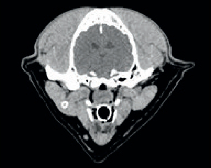
For upper airway, mouth and dental CT, the patient's mouth should be braced open with a radiolucent aid. A needle cap or tongue depressor works well. This better separates the tissues inside the mouth to help when reporting these regions. Any head imaging should also aim to use radiolucent endotracheal tubing to avoid streaking artefact in an already difficult to image area.
Post processing
Once the images are acquired, multi-planar reconstructions are used to review the imaging. As the images are 3D these can be reformatted in any plane, but the standard planes are transverse, dorsal and sagittal to the area of interest. All imaging studies are saved at the modality as DICOM (digital imaging and communications in medicine) files. This is a file type that contains hidden patient and study information within each image. Any good quality DICOM image viewing program will be capable of this reformatting, however, it is also common practice to reformat into the three planes at the modality for ease of viewing from the clinic PACS.
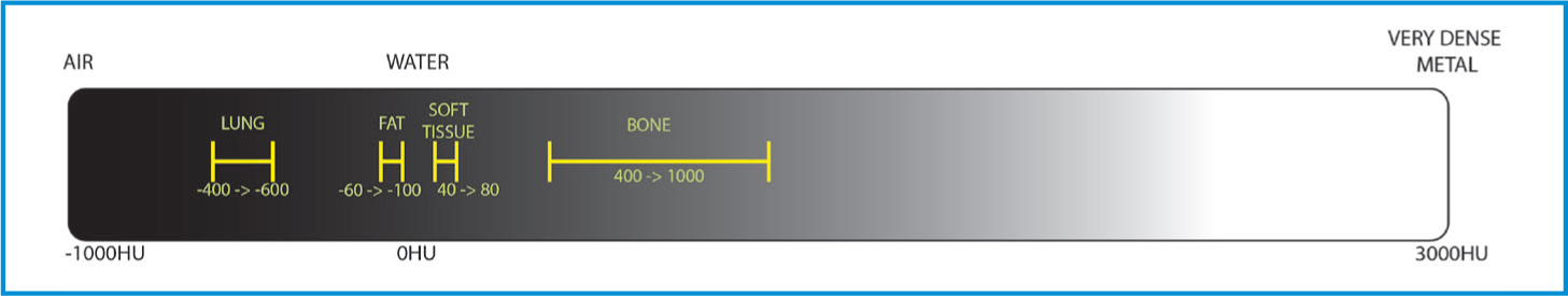
It is also possible to choose the ‘windows’ in which to view images. Traditionally a range of windows is used for each region. CT images collect a large volume of density information. Each of these densities is measured in ‘Hounsfield units’ or HUs. This is a relative quantity measurement used to produce the greyscale images. This is a scale defined by an attenuation co-efficient where distilled water is 0 HU, air is -1000 HU and the scale goes up to over 3000 HU for dense metals (Bell, 2021). If all the greys were available to visualise in a single image, the image would be non-diagnostic. Instead, the range of greys is chosen based on the radiodensity of the tissue type that is to be optimised.
A range of standard windows are used when evaluating CTs, but the most common are bone, soft tissue, lung, and brain or spine windows (Figures 10 and 11). While these are all in a standard range, they can be individually adjusted for user preference and machine variability. A window centre or level is chosen on the HU scale (Figure 12) as a midpoint, and then a window width chooses the range of greys either side of that HU.
Each of the body part algorithms is also run through a reconstruction kernel, that, like a filter on a photo, may have an effect on spatial resolution and noise, sharpening and softening the image (Lee et al, 2019). For this reason, simply changing the window on the bone algorithm may not provide a good soft tissue image. Therefore, while windowing is an effective tool for evaluating images, reformatting all the appropriate algorithms is still essential.
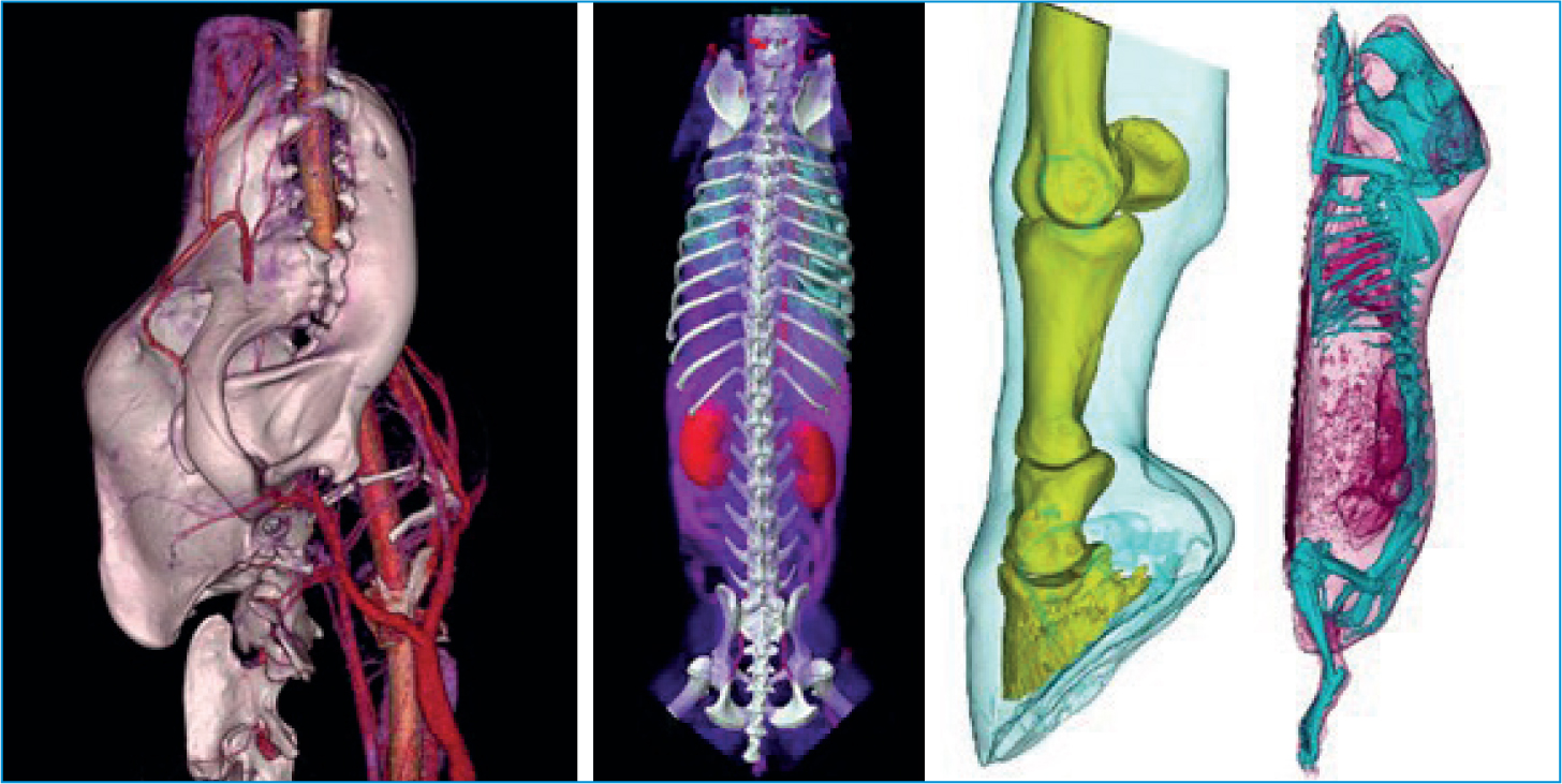
Another popular reconstruction method is 3D volume rendering. These are highly subjective and will differ from creator to creator, so it is important to understand they cannot be used for diagnostic measurements. However, they are great for visualising difficult to see structures or to demonstrate the extent of pathology to clients or staff not familiar with 3D imaging (Figure 13).
Contrast
Soft tissues throughout the body share similar radiodensities and therefore can be hard to differentiate between in modalities that use x-ray. To avoid this, contrast is used to highlight various features. The media used are typically radio-dense and appear bright on the images. Barium is administered orally for gastrointestinal tract imaging and iodine-based contrast medium can be used intravenously (IV), intrathecally, or less commonly, directly into joints, tendons or draining tracts. The IV contrast disperses throughout the body via the circulatory system. Vascular anomalies such as some neoplastic masses will then contrast enhance and be easier to diagnose on CT. The use of a pressure injector and bolus tracking CT software also allows for arterial and venous phase imaging by tracking and scanning the contrast bolus. Contrast is essential in the diagnosis of congenital abnormalities such as shunts and ectopic ureters, neoplastic growths and intervertebral disc disease (Bertolini, 2017).
Contrast-induced nephrotoxicity is a well-documented adverse affect of contrast media use in human medicine (Kirberger et al, 2012). The literature in veterinary medicine is far less extensive, but as a precaution, bloodwork to establish healthy kidney function, and intravenous fluid therapy is encouraged pre- and post-contrast procedures, in all patients. Contrast should only be used in renally compromised patients when absolutely necessary.
Radiation safety
CT users must always be cognisant of the risk to all parties associated with using apparatus that produces ionising radiation. The radiation doses are significantly higher than that of traditional x-ray and as such veterinary practitioners should endeavour to keep unnecessary scanning low, and personnel out of the room. There are strict standards around the use of such machines, so all users in the practice should be up to date with the relevant health board training and/or licensing requirements.
Conclusions
CT is an incredible modality with a diverse range of applications. Scans can be acquired in less than a minute, significantly faster than a 20–30-minute long magnetic resonance image or the time multiple x-ray acquisitions may take. The 3D information attainable can play a vital role in diagnosing and treating a huge variety of veterinary patients. To ensure acquisition of high-quality diagnostic images for best outcomes for patients, it is essential that users have a thorough understanding of the process by which images are acquired and viewed, and the artefacts they will commonly encounter.
KEY POINTS
- Computed tomography (CT) is a useful modality with many applications, but the risks of ionising radiation to both users and patient must always be considered.
- Just as in plain film radiography, despite many algorithms being pre-set by the modality, care should be taken to review all acquisition factors before each scan, and the variables adjusted for individuals.
- CT imaging is subject to significant artefact if appropriate factors are not selected. The use of breath holds and appropriate patient positioning will significantly improve image quality.
- For a diagnostic scan, much of the work is done after acquisition when reconstructing the data into studies in three planes and suitable windows.
- Three-dimensional volume rendering is a valuable tool for visualising the data, but its accuracy is variable and care should be taken when making prognostic decisions based on these models.
- The use of contrast media can greatly improve the visualisation of soft tissue anatomy and other vascular structures.