In order to perform safe and effective dental, oral and maxillofacial surgery, a practice must ensure its equipment is well maintained and in good working order. This article discusses the correct maintenance of dental machines and equipment.
Dental machine — initial set up
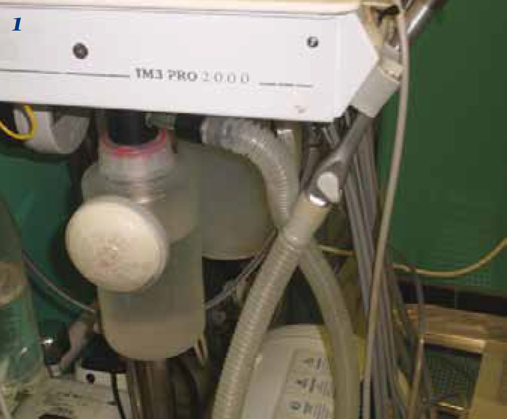
Most compressor driven dental machines should be mounted on four castor wheels to facilitate their movement around the operating table, and the height adjustment knob should be checked for correct functioning to ensure the dental machine is at an appropriate height for the operator and within easy reach (Gorrel, 2004). The waste collection container (Figure 1.) should be screwed in place under the control panel, if fitted on the machine.
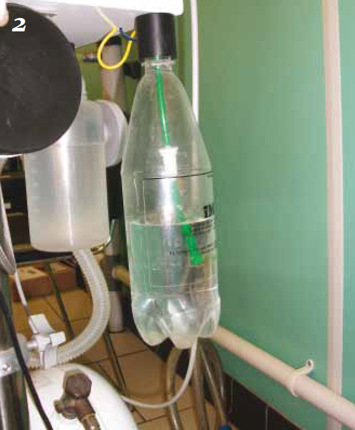
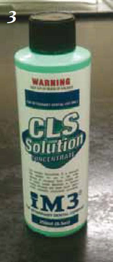
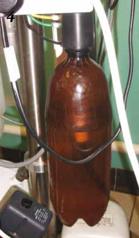
The clear plastic bottle is for distilled water and should be filled to the black fill-line indicated on the bottle (Figure 2.). With the tubing sitting inside the bottle it should be screwed in place, taking care to not overtighten the bottle. If there is an amber coloured bottle, this should be filled with the light-sensitive chlorhexidine (CHX)-based flush solution (Figure 3.) provided by the manufacturer at the correct dilution. Again this bottle should be screwed into place when the tubing has been inserted, taking care not to overtighten it (Figure 4.). Distilled water should always be used as it helps to prevent mineral and bacterial build-up in the dental machine.
Coolant system
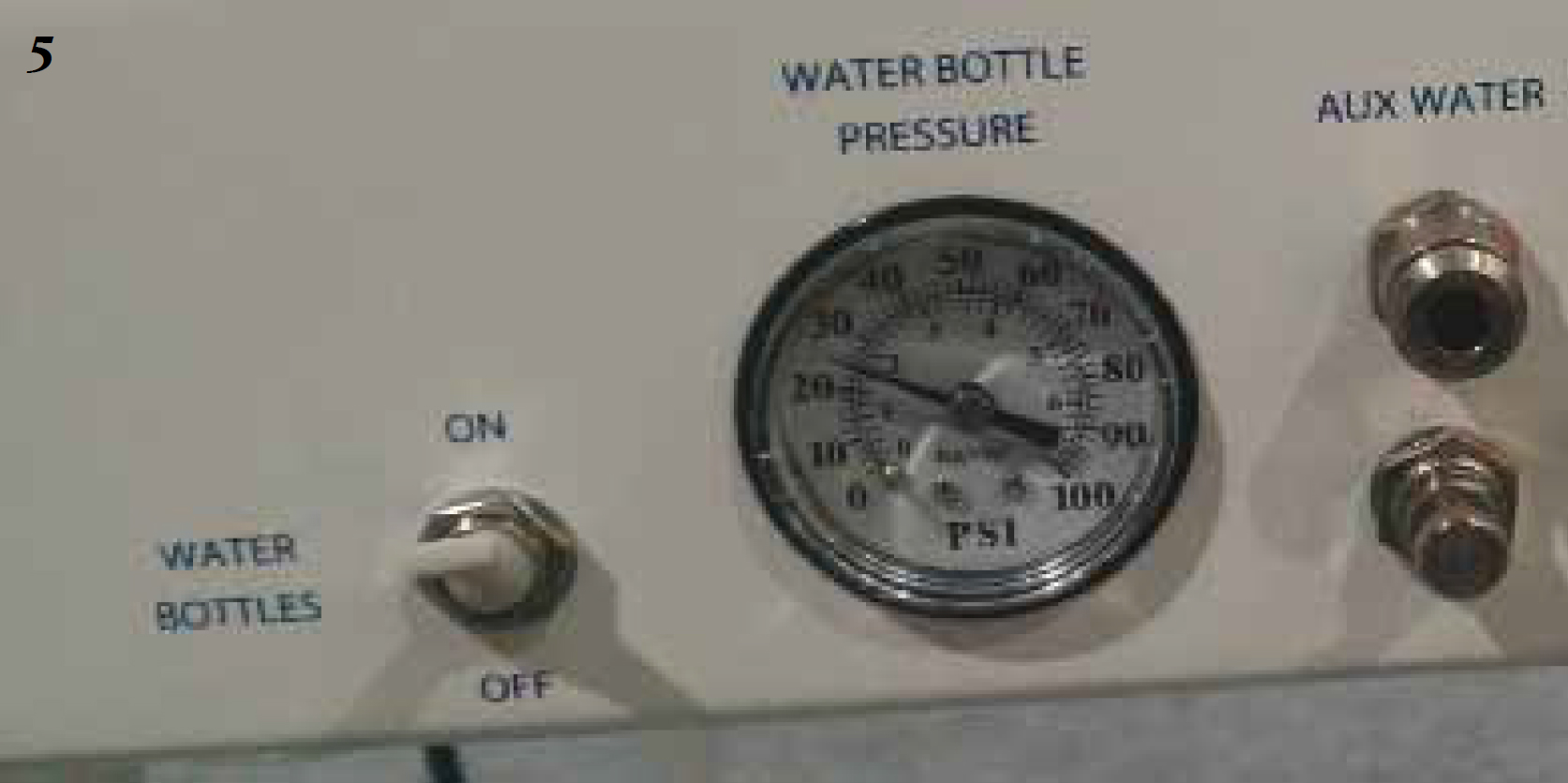
When the machine is switched on for the day the water and CHX bottles need pressurizing by turning the coolant bottle pressure switch to ON (Figure 5), and depressurizing at the end of the day. When the water bottles are removed for refilling during procedures, the coolant system should be depressurized prior to removing the bottle(s). If the dental machine features both of these sources of fluid there will be a switch/toggle to allow the operator to switch between the two during a procedure (Figure 6).

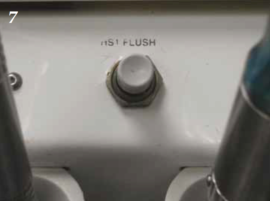
Some machines have the feature of a CHX flush system. When the operator takes their foot of the pedal having used the high speed (HS) hand piece the turbine still revolves for a few seconds, which creates a centrifugal pump action; this sucks air and fluid back into the hand piece from the oral cavity that could contain viruses and bacteria. A CHX flush system allows the operator to press a button for 1 second (Figure 7) to flush 1 to 2 ml of CHX into the air line of the HS hand piece, which should be allowed to stand for around 2 minutes before the operator then depresses the foot pedal to force the solution through the head of the hand piece to sanitize it.
In-line filters are located in the distilled water and CHX bottles which stop particles from entering the system and thus blocking the hand pieces. These filters need checking regularly, and if they start to look dirty due to the build up of filtered materials they need replacing (can be seen in Figures 2.and 4); replacement filters should be ordered from the manufacturers, or be ones recommended by them. The bottles should be removed regularly for cleaning, and can be sterilized using ethylene oxide or cold chemical solutions.
The tip of the air/water syringe can be removed by depressing the outer rings and pulling on the tip for cleaning. The air/water syringe is an invaluable tool on the dental machine, used during a procedure to irrigate and lavage the mouth (Gorrel, 2004), so it should be function checked prior to every procedure.
High-speed hand piece
The HS hand piece is used primarily for sectioning multi-rooted teeth (Gorrel 2004), and there are certain rules to follow with regards to their maintenance.
When the HS hand piece has finished being used for the day, the outside surfaces must be cleaned thoroughly with some disinfectant wipes (Figure 8) to remove all traces of blood and dental debris. It would be a good idea at this point to use the CHX flush system, as previously mentioned.

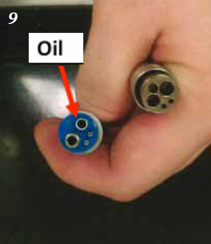
The hand piece should be unscrewed from the grey cabling and lubricated with oil; the oil provided by the manufacturer should always be used, and 2 to 3 drops should be placed carefully in the smaller of the two large holes on the bottom of the hand piece (Holmstrom et al, 2004) (Figure 9.). The hand piece should be reattached and the foot pedal depressed for 5 to 10 seconds to ensure the oil reaches the turbines.
When the HS hand piece is being operated there MUST be a bur inserted, whether this is a surgical bur or a safety/blank bur. If operated without a bur in place it will damage the turbines/chuck (Holmstrom et al, 2004) over time and the hand piece will gradually lose grip on the burs inserted, which is a massive health and safety risk.
Following lubrication the hand piece should be unscrewed, have the bur removed and be placed into an autoclave bag. The bur needs to be removed for autoclaving due to the expansion and contraction of the metals during the sterilizing cycle, and the hand piece should be autoclaved at 135°C or less. Having been sterilized the hand piece should be lubricated again and attached to the dental machine, have a bur inserted (surgical or safety) and operated as described above to ensure the oil reaches the turbines. After 30 minutes of usage it is advised the hand piece is lubricated one more time as part of an optimal maintenance regimen.
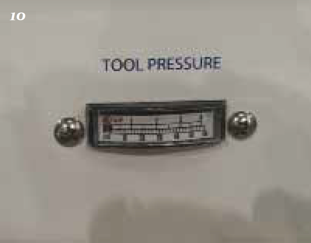
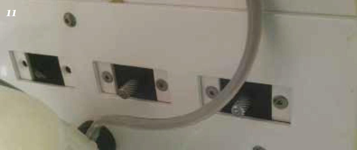
The HS hand piece should operate at around 40 pounds per square inch (psi — pressure) at a speed of 350 000 revolutions per minute (RPM), the range being 200 000–400 000 RPM (Holmstrom et al, 2004). The operating pressure can be checked on the hand piece pressure gauge of the control panel (Figure 10) and altered using the pressure adjustment knobs on the underneath surface of the control panel (Figure 11).
Low-speed (LS) hand piece
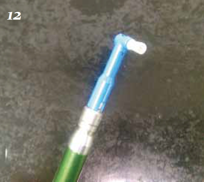
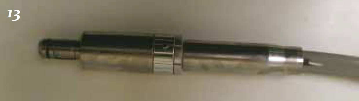
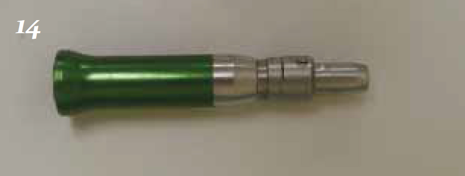
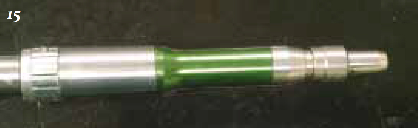
A LS hand piece is primarily used for polishing teeth and should preferably have entire disposable prophy heads for attachment (Figure 12). The hand piece generally comes in two pieces; the first part (lower part — Figure 13) is the motor which attaches to the grey cable of the dental machine, and there are a variety of second parts (upper parts — Figure 14) that attach onto the motor unit to complete the hand piece (Figure 15).
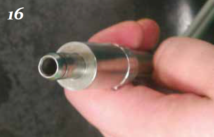
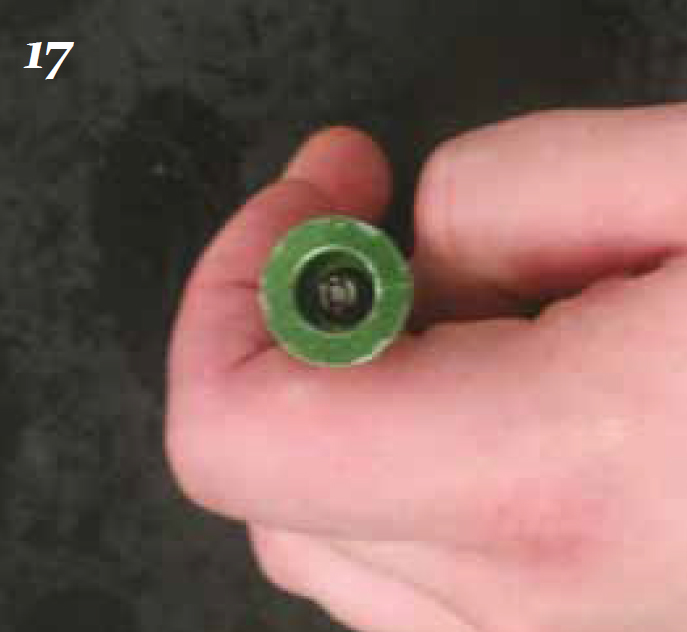
These LS hand pieces should be maintained in exactly the same way as the HS hand pieces with regards to the way they are cleaned after use, lubricated, autoclaved, lubricated and reassembled for use. The only extra step required is to ensure the attachment piece that pushes onto the motor unit is also lubricated (Figures 16.and 17).
The LS hand piece should operateat 20 000 RPM to maintain motor speed and torque, however, this is too powerful for the purposes of polishing and could lead to thermal damage of the pulp. Thus, polishing should be performed at 5000 RPM or less; most of the LS attachments used for polishing are 4:1 reduction heads, thus they automatically reduce the 20 000 RPM to 5000 RPM. The operating pressure for the LS should again be checked on the hand piece pressure gauge, and altered as for the HS hand piece.
Compressor
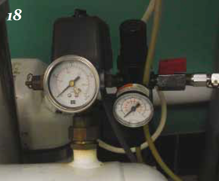
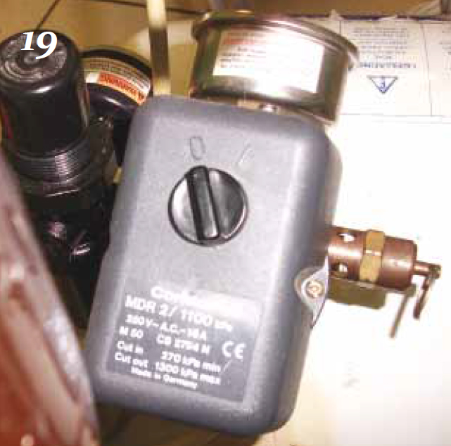
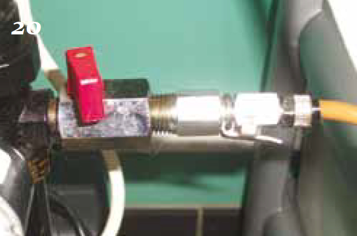
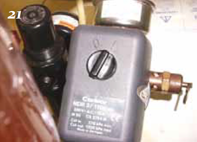
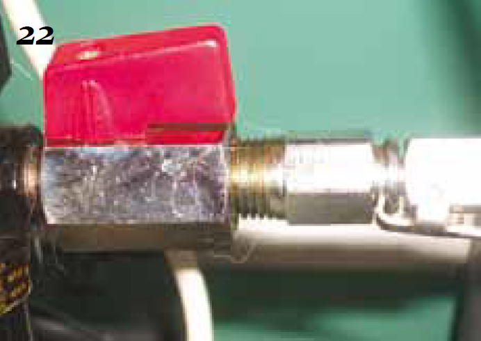
The compressor is an essential part of a dental machine as it supplies the air to run the hand pieces and to pressurize the water and coolant systems. The air tank should be running at around 110 psi (7.5 BAR), and the regulator about 70 psi (5 BAR) (Figure 18.) The machine should be plugged into the mains supply and the air tank on/of valve should be in the OFF position (Figure 19.), and the air to dental machine valve should be in the OFF position (Figure 20.) Switch the plug socket on to supply electricity and turn the air tank valve to ON (Figure 21.); the motor should then run and will stop when it reaches the appropriate 110 psi working pressure. The grey air line from the dental machine to the compressor can then be connected and the air to dental machine valve turned to the ON position (Figure 22.)
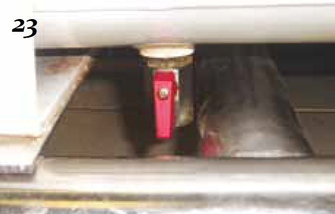
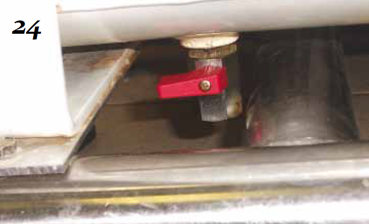
On a weekly basis the condensation buildup in the compressor needs to be drained away (Holmstrom et al, 2004). To do this the pressure in the air tank needs to be reduced to around 10 psi by turning the air tank OFF. When 10 psi is reached the condensation/moisture can be drained into a receptacle by opening the valve at the bottom (underneath) of the air tank; this should be opened slowly to avoid being sprayed in the face (Figure 23.), and closed again when drainage is complete (Figure 24).
Powered scalers
Powered scalers are preferred to hand scalers as they save a lot of time during a procedure when removing calculus deposits. Ultrasonic piezoelectric scalers are commonplace in practice and operate at between 20 and 30 kHz depending on the make (Gorrel and Penman, 1995). The other main type of powered scaler is a magneto-restrictive (Cavitron®, e.g. Dentisply professional) micromotor-type.
At the start of the day the hand piece should be lubricated before assembly if necessary; this should be checked in the manufacturer’s instructions, because some power scalers require hand piece lubrication and some do not.
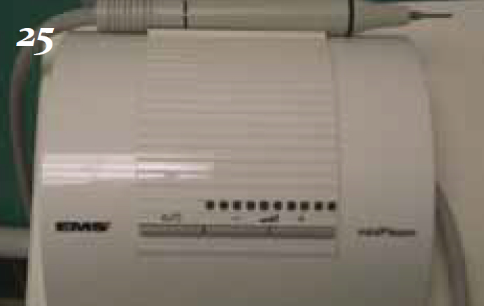
When the hand piece is assembled the power and water flow should be put on the maximum settings (Figure 25). The foot pedal should be activated and the hand piece held over a sink or drain until water starts coming out, which should be allowed to run through for around 2 minutes before the scaler tip is attached, ensuring if it is a screw in tip it is not overtightened. The power should then be turned down to the minimum setting possible for the procedure, as should the water flow; there only needs to be a fine mist coming out of the tip.
At the end of the day’s procedures the tip should be removed and the hand piece disassembled. All surfaces of the scaler unit, tubes and hand piece should be disinfected with an appropriate chemical such as an alcohol-based surface disinfectant, and the tips should be sterilized either in an autoclave or using cold chemical solutions. The operator should check how the manufacturer recommends sterilizing the hand piece: autoclave, cold chemicals or simply disinfection of the surface.
Hand instruments
It is essential hand instrument tips are well maintained and are kept sharp to avoid damaging patient tissues. Hand scalers, curettes, luxators, elevators and periosteal elevators all have sharp working tips that need to be re-sharpened before every use after being autoclaved, as autoclaving dulls sharp edges (Gorrel and Penman, 1995).
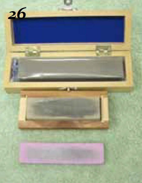
A set of stones (Figure 26.) is required to sharpen instruments correctly, and the person sharpening the instrument should put a drop of oil onto the stone and rub it in, which helps the passage of the instrument over the stone and reduces the chance of metal shards embedding in the surface of the stone (KAB Dental Equipment, 2011). Some stones do not require the use of oil (you must check which type you have purchased), such as aluminium oxide varieties. Stones can also be made from ceramic and silicone carbide, and some popular types are Arkansas and India stones, all of which can be purchased in different ‘grades’ according to how coarse or abrasive their surfaces are.
For hand scalers and curettes, the working edge of the tips should be placed fat against the stone’s surface so the open angle between the instrument face and the stone is approx 110°; this ensures there is an angle of 70° between the face and the blade (Holmstrom et al, 2004). The stone can remain stationary while the operator moves the instrument along it, or the stone can be moved against the stationary instrument.
Via either method, the edge of the working tip should be moved forwards and backwards, or up and down against the stone about five times, ending on a forwards or downwards stroke. This action should be repeated for each of the working edges to be sharpened.
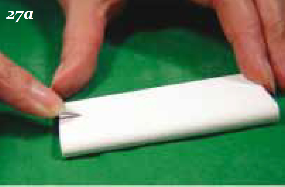
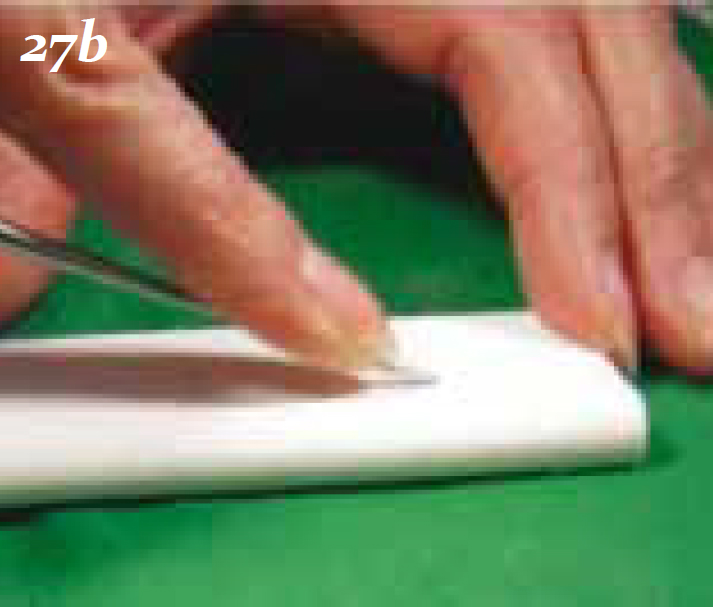
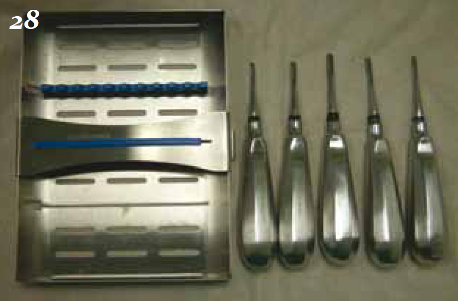
Luxators, elevators and periosteal elevators should be held with the body of the instrument in the palm of the hand with the index finger extended towards the tip of the instrument for stability. The tip of instrument should rest on the stone at an angle of approximately 10° to 20° (Figure 27a); the operator should then push the instrument along the surface away from them (Figure 27b), and repeat this action three to five times. The moving stone technique can also be employed here, and ideally the concave part of the working tips of luxators and elevators should be sharpened on a matching concavity of the sharpening stone (Hol-mstrom et al, 2004). Special conical-shaped stones are available. To keep these hand instruments safe between procedures and during autoclaving it is ideal to purchase some metal trays to sit them in; this will protect the working tips (Figure 28.).
Conclusion
The maintenance of dental equipment should be part of the daily routine in practice to ensure it is all in good working order for the next patient. Poorly maintained equipment can lead to poor procedures being performed, which are lengthier and ultimately a risk to the anaesthetized patient.