
This article aims to outline and evidence the benefits of oral radiography in veterinary practice; it is an indispensable tool for quality oral health care provision. The article will outline the indications for oral radiography, before considering the equipment needed to obtain the radiographs, the techniques required to produce images of high diagnostic quality, and some of the common faults associated with the procedure.
Oral radiography in practice
Radiographic findings are a key element in decisionmaking, thus radiography is a vital tool in veterinary dental diagnostics; it is indispensible in human dentistry, and dental radiographs are considered an essential part of a comprehensive oral examination (Crossley, 2006; Verstraete, 2007). Crossley (2006) highlighted that tooth roots are the largest part of most teeth, which are hidden from view along with their supporting structures. This fact combined with high client expectations nowadays made him question why radiography is not an integral part of the dental service offered by veterinary practices. Crossley (2006) suggested that some veterinarians may have concerns regarding the costs associated with taking dental radiographs, but rightly stated that the decision regarding costs lies with the clients and not the veterinarians. He also considered the fact that many people view oral radiography as difficult; everything is difficult at first, and proficiency comes with practise. Crossley (2006) stated that not knowing all of the facts prior to treatment puts patients at risk, which is entirely unacceptable, therefore oral radiography is essential in every practice providing a dental service. Consider how many orthopaedic surgeons would perform surgery without radiographic control.
Radiography assists the veterinary surgeon in:
The information provided by oral radiographs is critical for a full diagnostic examination and the formulation of a treatment plan. In addition, Smithson (2006a) stated that accurate treatment is not possible without an accurate diagnosis. To obtain quality diagnostic dental images, the radiographer must pay attention to the recommended steps of radiography and processing; positioning, technique and the handling of films during processing are all important (Smithson 2006b). Oral radiography is a little more technically demanding than standard radiography, but the concepts are relatively straightforward and practise does indeed make perfect.
Indications
There are many reasons why oral radiographs are required in veterinary medicine, and all veterinary surgeons performing ‘dentals’ in practice should be proficient in obtaining and interpreting oral radiographs to inform their diagnosis and treatment plan.
The indications for oral radiography in veterinary dentistry include:
All of the above conditions or problems would be very difficult, if not impossible, to assess, diagnose and treat without radiography, and the benefits of oral radiography for the surgeon, nurse, owner and patient should now be clear. Oral radiography is not only vital for accurate diagnosis and treatment, but also for: reducing the general anaesthetic time, which is beneficial for the animal and will reduce costs to the owner; decreasing the trauma associated with procedures, such as not trying to extract roots that have evidently resorbed having taken a radiograph of them; increasing the speed of the procedure, as the veterinary surgeon knows exactly what they are dealing with below the gingival margin; and increasing the efficacy of treatments, as doing a procedure correctly first time will reduce the need for second and potentially more difficult surgeries (Caiafa, 2007). It must be remembered that oral radiography is also an area where interested veterinary nurses can get involved and contribute to excellent dental service provision. Veterinary nurses are highly trained professionals who have studied radiography during their training, and mastering oral radiographic techniques will add to their skills-set in this important area of clinical practice.
Equipment — x-ray machine
The first piece of equipment needed is an x-ray machine (Figure 1), preferably a dental x-ray machine. The kilovolt peak (kVp) controls the quality of an xray beam (the penetrating power), the milliamperage (mA) controls the quantity of x-rays produced, and the seconds (s) setting controls the time, or length of the exposure. As discussed by Niemiec et al (2004), there is minimal variation between the oral tissues, the teeth and surrounding bone, therefore dental x-ray machines have a constant kVp and mA; time (s) is the only variable, and is measured in seconds or ‘pulses’, where 1 pulse is equal to 1/60 of a second. The kVp and mA settings are variable between manufacturers, but are typically set between 50 and 90 kVp, and 5–20 mA (Niemiec et al, 2004; Smithson, 2006a). Niemiec et al (2004) explained that a dental x-ray machine can be calibrated to automatically select the length of exposure, considering the patient size, the tooth and the speed of the films used; the operator's required combination are selected from, and inputted on the machine's control panel, which then chooses the most appropriate exposure length. This removes a lot of the ‘guess work’ associated with selecting correct settings, and is particularly useful for those not experienced in oral radiology.
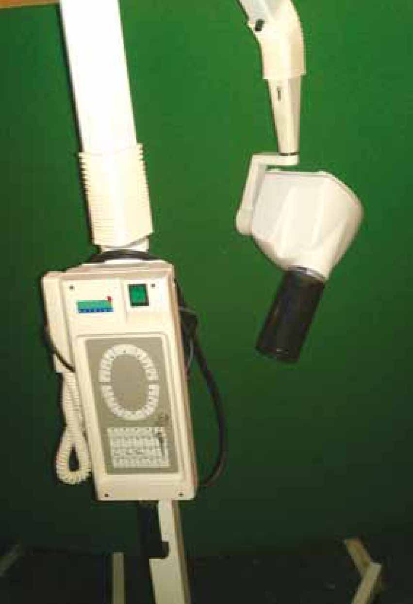
As discussed by Smithson (2006a), a dental x-ray machine is preferable to a standard x-ray machine because the head of the machine can be rotated and tilted around the patient's head to ensure the correct alignment of the primary beam, which makes the whole process more efficient. When using a standard x-ray machine the patient needs to be positioned accurately using many positioning aids to ensure the correct alignment is achieved with the fixed primary beam; this is much more difficult and time-consuming. Therefore, a wall-mounted or mobile dental x-ray machine is an essential piece of equipment in a practice offering a dental service, with a wall-mounted one being preferable as it reduces the amount of floor space being used.
Dental x-ray machines have a collimation cone, which is usually lead lined. The film focal distance (FFD) is dictated by the length of the cone, and is typically between 20 and 50 cm (Smithson, 2006a; Caiafa, 2007). The collimation cone helps to reduce scatter, helps to concentrate or focus the primary beam on the primary area of interest, and thus radiographs are obtained with a greater level of detail (Caiafa, 2007).
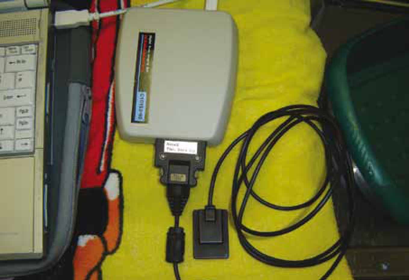
It must be remembered that any dental x-ray machine can also be used with a digital oral radiography system too (Figure 2), and digital systems reduce the ionising radiation exposure to patients so are preferable for health and safety reasons (Caiafa, 2007).
Equipment — films
The films used are intra-oral, non-screen films. As outlined by Smithson (2006a), intra-oral non-screen films produce images of high diagnostic quality with high resolution, and because they are tiny films that can be placed within the oral cavity there is no superimposition of adjacent oral cavity structures; all of these factors produce superior results when compared with using standard radiography equipment and techniques to image the oral cavity and dentition.
There are different sizes of intra-oral films available for use, which are: paediatric films (size 0 and 1); periapical films (size 2); and occlusal (size 4). Sizes 2 and 4 are most useful in small animal dentistry, and additionally sizes 0 and 1 are useful in cats and exotics (Figure 3). The structure of the film unit is very simple and includes:
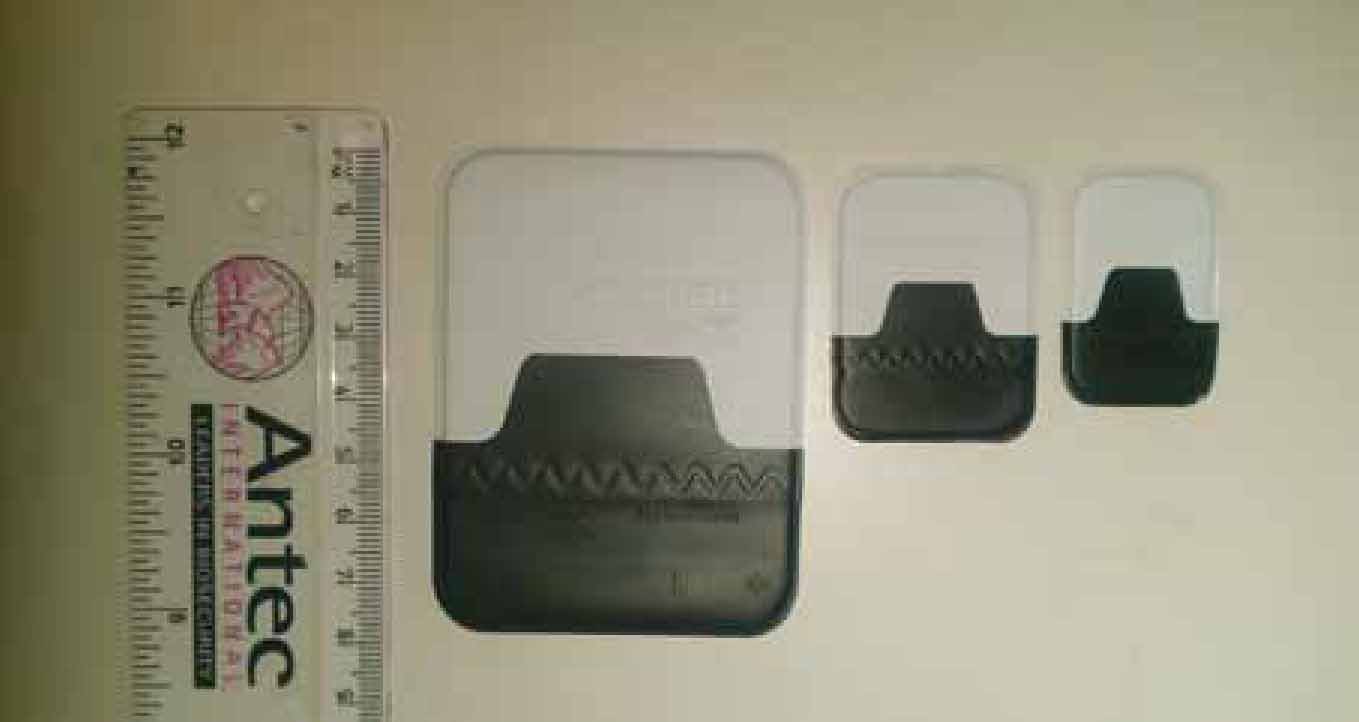
In one of the corners there is a raised dimple which acts as a marker, and is a feature of all of the layers mentioned above (Figure 3). This dimple always faces towards the primary beam and the front of the mouth as a standard positioning rule as it aids the person viewing the film in deciding which side of the oral cavity, and thus which individual teeth are depicted in the image. This negates the need for left/right markers, which would be impossible to use with such a small film (Smithson, 2006a; Caiafa, 2007).
Niemiec et al (2004) outlined the key differences between the two most common types of dental films, which are the ultra-speed ‘D’ and Ektaspeed ‘E’ films. Silver halide crystal size in the emulsion of x-ray films dictates the ‘speed’ of a film, with larger crystals resulting in a faster film that requires less exposure, but produces a grainier final image. Niemiec et al (2004) explained that ‘E’ films have larger silver halide crystals and require half the amount of radiation to expose them compared to ‘D’ films, and in fact the difference in image quality is negligible. Therefore it is preferable to use ‘E’ films to reduce the amount of ionising radiation the staff and patients are exposed to, and this will also reduce the wear and tear on the machine. Niemiec et al (2004) recommended that people new to oral radiography should start with ‘D’ films and progress to the faster ‘E’ films with experience. They also recommended that new operators use size 4 occlusal films when they first start taking oral radiographs to ensure they do not miss any of the oral structures, before moving onto the smaller and more cost-effective size 2 films, which require more accuracy in technique.
Equipment — processing
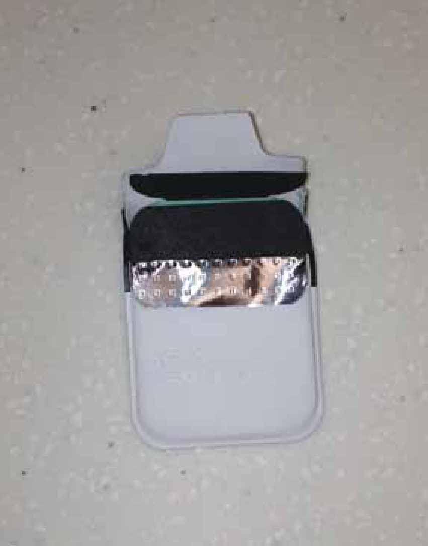
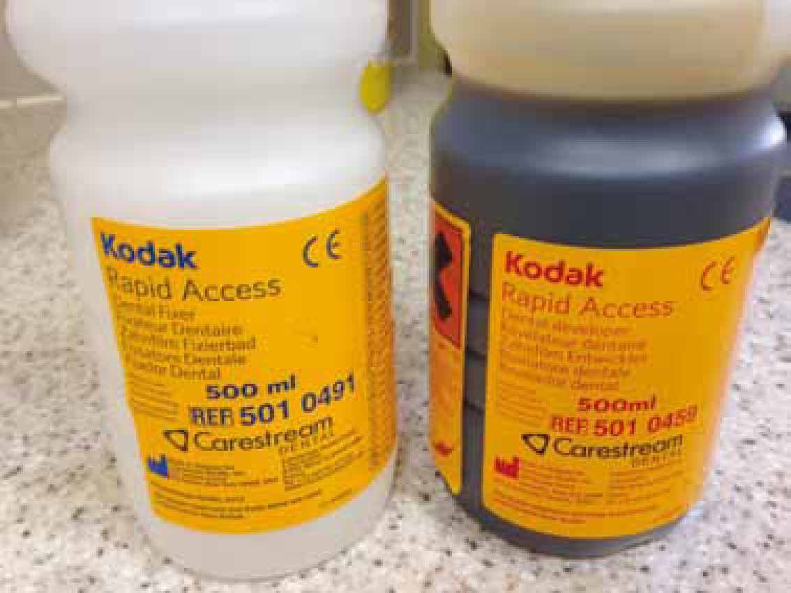
Films can be processed using standard x-ray developer and fixer chemicals in the dark room. The veterinary nurse must remove the film from the packaging, attach it to a clip and dip it in the developer for 4 minutes, rinse it and then dip it in the fixer for 10 minutes. This is a more time-consuming way to develop the films, so rapid developer and fixer solutions are recommended (Figure 5), which are much more concentrated than standard solutions, to reduce the processing and thus anaesthesia times (Caiafa, 2007). These rapid chemicals are used in the chair-side units described below.
Automatic processors can be purchased to process intra-oral films, but these can be expensive and can also malfunction. There are also self-developing films available for use, which contain the film in one pouch and the processing chemicals in a second pouch. Once the film has been exposed, the chemicals are squeezed through to the film, agitated there for 1 minute before the pouch is opened and the film rinsed ready for viewing.
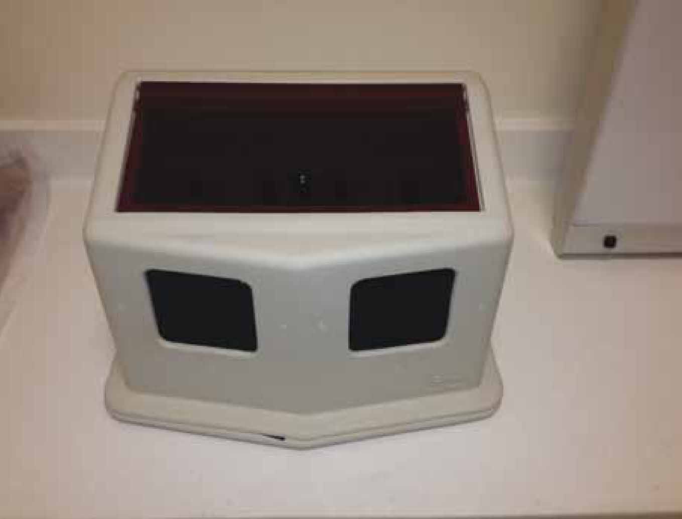
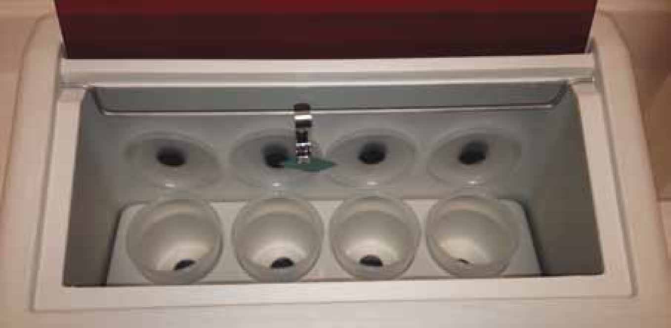
The recommended way of processing intra-oral films involves the use of a chair-side processing unit, which is a plastic box with an orange tinted plexiglass window (Caiafa, 2007) (Figure 6). The operator pushes their arms through the arm holes, unwraps the film, places an individual clip onto the corner of the film and proceeds to dip and agitate the films methodically in differing solutions. There are four cups of solutions (Figure 7), and from left to right the operator should do the following to ensure the film is processed correctly:
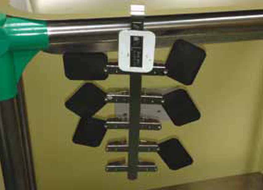
Following the final fixing period and rinsing, the film should be rinsed well under running water to remove the ‘soapy’ feeling, before being clipped to a tree hanger to dry before archiving (Figure 8).
Digital systems obviously remove the need for all of the processing methods described above, because once the sensor is exposed the image appears within seconds on the computer screen (direct-to-digital), or the sensor plate is processed as per a standard computed radiography system via the plate reader, and then the image is displayed on the computer screen.
Technique
Niemiec et al (2004) outlined a five step procedure to follow when taking intra-oral radiographs, which are summarised below.
Step one: patient positioning
The area of interest should be closest to the x-ray beam. As a general rule the patient should be in ventral recumbency to image the maxillary teeth, dorsal recumbency to image the mandibular canines and incisors, and in the appropriate lateral recumbency to image the mandibular premolars and molars.
Step two: film placement in the mouth
The dimple previously mentioned should be tubeside (facing the primary beam) and rostral. The film should be placed to cover the entire tooth and root, with care taken to ensure the film is pushed in a little further to ensure the root apices are included in the final image (and 3 to 5 mm of bone beyond the apex to detect periapical pathology). The film should be placed as close to the tooth as possible, touching it preferably, to minimise distortion on the final image.
Step three: positioning the beam
There are two techniques used to image the teeth, which are the parallel technique and the bisecting angle technique, which are explained below. Once the angles have been finalised the head of the x-ray machine should be positioned in such a way that the correct angle is achieved, that the collimating cone is as close to the patient's anatomy as possible, and the entirety of the film is covered by the cone.
Step four: setting the exposure
As previously mentioned, dental x-ray machines do vary, but the operator needs to choose the most appropriate setting for the patient species, size and tooth being imaged. The operator must remember that for cats there is generally just one setting for mandibular teeth, and one for maxillary, and choosing a particular tooth for cats will automatically cause the machine to default back to the dog settings, resulting in an over-exposed final image.
Step five: expose the film
Dental x-ray machines typically have a hand-held exposure button on the end of a long cable that ensure the operator can leave the room during the exposure, or be at least 2 metres away from the primary beam. The operator should stand at 90 or 130° to the beam (to the side or behind). Most buttons are called ‘dead man's’ buttons, which means they must be held down for the duration of the exposure, until a light and/or audible cue indicates the exposure is complete. Removing a finger too early will interrupt the exposure process.
Technique — parallel
This is the technique veterinary professionals are familiar with when obtaining diagnostic radiographs. The film is parallel to the object, and the film is perpendicular to the primary beam. With regards to intra-oral radiography, the parallel technique can only be used to image the mandibular premolars and molars, where the film can be placed between the tongue and the teeth (object) with the patient in lateral recumbency, and the primary beam is aimed at the film perpendicularly (Figure 9). In animals the parallel technique is not possible for any of the maxillary teeth because animals do not have arched/concave hard palates as humans do, and is not possible to image the mandibular canines or incisors due to the flat mandibular symphysis.

Technique — bisecting angle
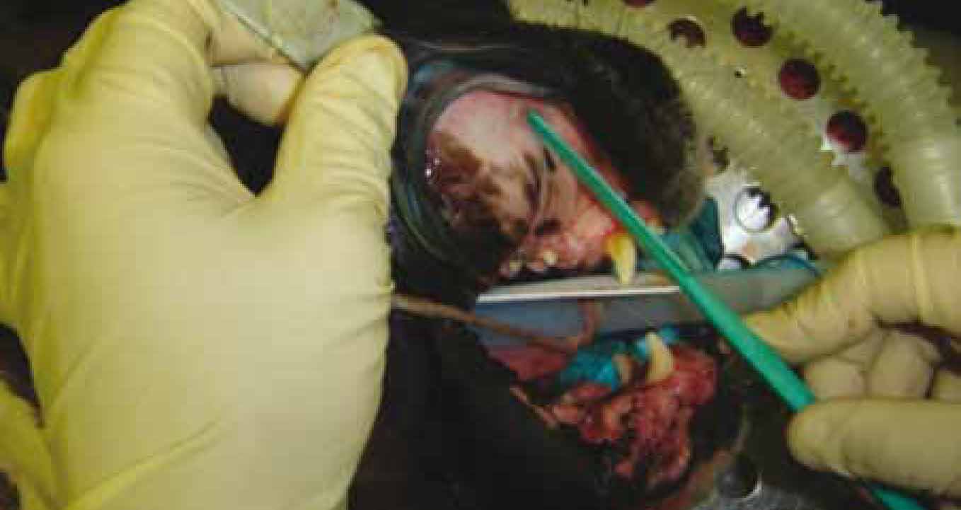
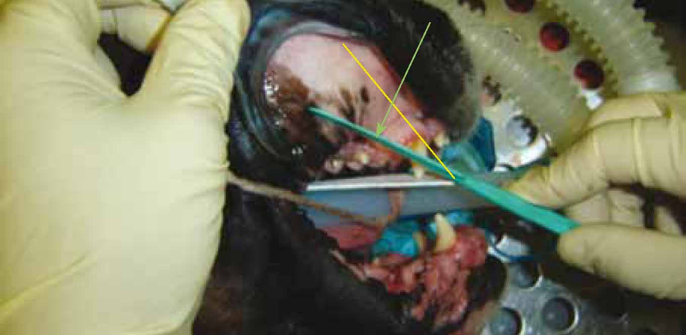
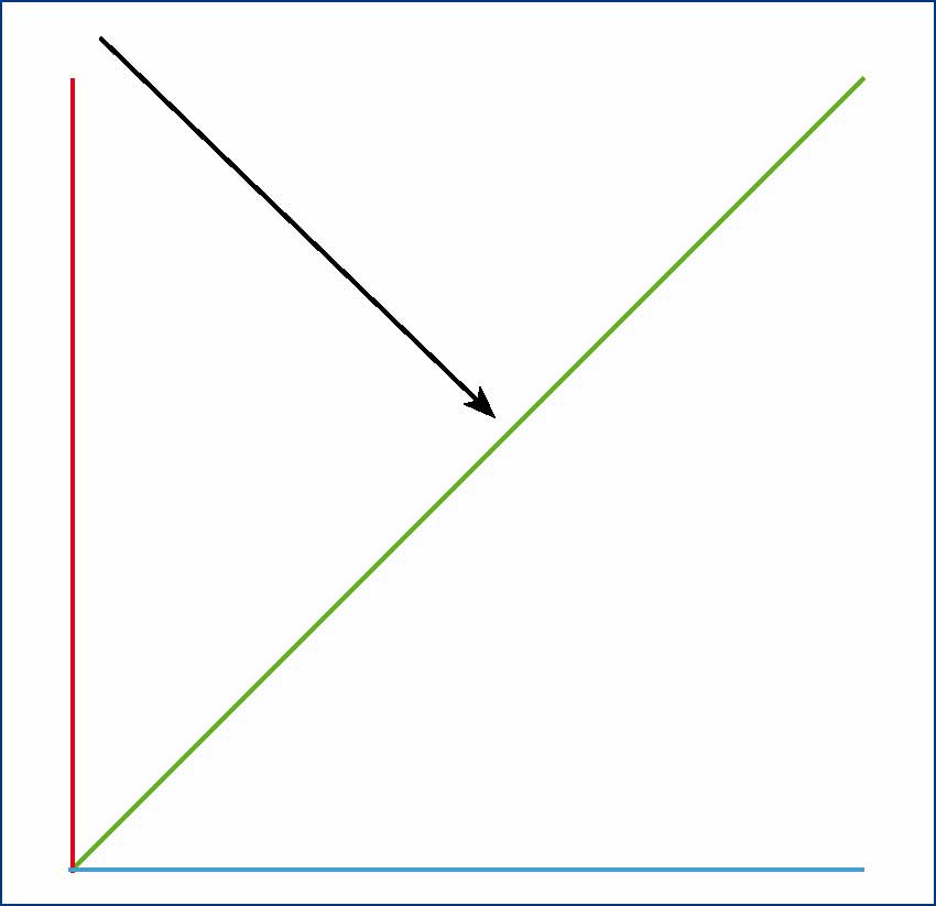
This is the most common technique for small animal intra-oral radiography due to the anatomical differences mentioned above. This technique utilises the theory of equilateral triangles to obtain a representative final image of the teeth. The operator needs to place the film as close to the tooth as possible, and pack it in place or stabilise it using tissue paper/sponge or other suitable material. They should then find and measure the angle between the film and the tooth/root (object) (Figure 10). When measuring the angle of the object the operator should find the line of best fit from the crown to the root apex; this will be the tooth (object) angle (Smithson, 2006a). This angle is then cut in half (bisected) (Figure 11), and the primary beam is aimed perpendicular to this bisecting angle (Figure 12).
Faults associated with all stages of oral radiography (Smithson, 2006b) are detailed in Table 1.
| Fault | Cause | Remedy |
|---|---|---|
| Inaccurate film positioning leading to missed anatomy (typically the root apices) | Allowing insufficient film area for the object being imaged. Inexperienced/novice operators | Use an appropriately sized film, ensure the film is placed to capture 3–5 mm of bone beyond the apices, and practise positioning regularly! |
| Incorrect bisecting angle technique | Incorrect vertical and horizontal angulation will lead to elongated images, foreshortened images and superimposition of other anatomy. Inexperienced/novice operators | Practise working out the angles on anatomical models as much as possible, as well as on live animals |
| Distortion | Film flexion when positioned | Keep films flat to the object and support with tissue paper/sponges |
| Underexposure (pale, indistinct image) and overexposure (dark, indistinct image) | Incorrect x-ray machine settings | Follow the manufacturer's instructions and create a settings chart/guide |
| Pale, indistinct image | Underdeveloped due to exhausted chemicals | Ensure the chemicals are replenished regularly |
| Dark, indistinct image | Overdeveloped | Ensure the recommended developing times are adhered to |
| Brown image | Insufficient fixing | Ensure the chemicals are replenished regularly and the film is fixed for the recommended times |
| Dark marks | Error during developing | Ensure the clips are cleaned regularly, attach the clips away from the main body of the final image, and handle the films at the edges only |
| Pale marks | Fixer fault |
Rinse the film clips in water between processing, ensure chemicals are replenished regularly |
| Scratches | Poor handling of films | Handle films carefully when processing, and take care with long fingernails |
Conclusion
Intra-oral radiography is a fundamental tool in veterinary dentistry, and should be a standard part of any treatment plan in a practice that provides a dental service. The benefits of obtaining quality diagnostic images of the teeth and peridontium cannot be over-emphasised, especially when the majority of a tooth is not visible to the naked eye. Radiographs reveal a plethora of problems sub-gingivally, which will inevitably help the veterinary surgeon to perform quality, controlled, less traumatic and significantly less frustrating dental procedures. Intra-oral radiography is a more technically demanding procedure than standard radiography, but only until the operator evolves from a novice to experienced practitioner; practice does make perfect.