How to produce diagnostic orthopaedic radiographs

01 December 2010
10 mins read
Volume 1 · Issue 3
How to produce diagnostic orthopaedic radiographs

Abstract

Orthopaedic radiography can be challenging, but also very rewarding when good diagnostic radiographs are produced. This article explains the necessary theory required and details a step by step standard technique to achieve this. Positioning points and tips are given for the shoulder, elbow, pelvis and stifle.

This article aims to provide the reader with the necessary understanding and information to produce diagnostic orthopaedic radiographs. The results of a good radiographic examination can provide definitive information for diagnosis.

A diagnostic radiograph is one that maximizes the amount of information available from the resulting radiograph, enabling the radiologist or clinician to make a diagnosis and when necessary compare it with text book ‘normals’ and anatomical specimens.

In order to produce diagnostic radiographs it is important to use a standard technique; this involves looking at all aspects affecting the production of the radiograph.

The animal

Preparation

Animals are not uniform shapes and sizes and this needs to be taken into consideration when planning the radiographic examination. Orthopaedic cases may also present with various types of external device (fixators, dressings, casts etc), which may require some imaginative positioning and exposures to get the views required.

Before starting the radiographic examination adequate preparation of the animal should be undertaken. The coat should be clean and dry as a dirty and/or wet coat can cause radiographic artefacts (Dennis et al, 2010). Where possible dressings should be removed or reduced to a minimum taking the necessary infection control measures. Similarly collars and harnesses should be removed as they may overlie the area of interest.

Restraint

Adequate restraint is necessary to achieve the various views required in orthopaedic radiographic studies. Some views require the use of ties, e.g. stressed views of the carpus/tarsus etc, and in these cases general anaesthesia is required. The orthopaedic case can often be painful on presentation and therefore adequate analgesia and restraint (sedation or general anaesthesia) will be necessary. Sometimes for clinical reasons, e.g. dyspnoea, it may be necessary to radiograph the animal conscious. This requires time and patience, and will restrict the type of views possible, it will also increase the possibility of movement blur, but manual restraint must be avoided at all times, as stated in the Ionising Radiations Regulations 1999.

Positioning

Use standardized positioning – see orthopaedic technique.

The equipment

The X-ray generator, control panel, table and tube head.

Ideally they will have:

  • A wide range of kV, and independent selection of mA and s
  • Changeable film focal distance (FFD)
  • A rotating and tilting head
  • A table of suitable size with integrated Potter Bucky grid
  • A light beam collimator allowing both longitudinal and transverse restriction of the beam
  • Some method for securing ties
  • A cushioned table top mat (Figure 1).
  • Figure 1. X-Ray table and tube head.

    Cassettes and film screen combinations

    Ideally there will be:

  • Various sizes of cassettes available
  • The combination of a green rare earth screen with orthochromic film is recommended for orthopaedic radiography. This combination maximizes output while minimizing exposure, as it is very efficient at absorbing X-ray photons and fluoresces strongly with little afterglow
  • The slower the film, the smaller the film emulsion crystals and the greater the definition. Slow film/screen combinations are recommended for extremities and joint detail, and medium speed combinations for thicker tissue areas (see grids below) (Figure 2).
  • Figure 2. Cassettes of assorted sizes.

    Grids

    Use grids if the tissue depth is >10 cm, e.g. pelvis, shoulders. The Potter Bucky grid is the one of choice, it is easier to use and grid lines are avoided. If using a tabletop grid the pseudo focused type is the one of choice, it reduces scatter, but can be used for a range of FFDs (Figure 3).

    Figure 3. Potter Bucky grid.

    Positioning aids and markers

    Sandbags can be used to pull limbs forward, backward, away from the area of interest and to stabilize the patient. Ideally they will have removable covers for washing or be made of an easy clean material. They should be about two-thirds full to keep them flexible and of various sizes in width and length (Figure 4a).

    Figure 4. Assorted positioning and labeling aids. a) Sandbags. b) Foam shapes. c) Radiolucent cradles. d) Left/right markers and ties.

    Foam shapes are used to support areas and avoid limb/joint rotation. It is useful to have a variety of shapes and sizes including a mini set to use on cats and small dogs (Figure 4b). Wrapping in cling film is recommended as an infection control measure. The foam should be checked for radiolucency.

    Radiolucent cradles can used to support the main body of the animal in conjunction with sandbags, e.g. ventrodorsal (VD) extended view of the hips/pelvis (Figure 4c).

    Markers and ties can be used with either sandbags or table anchor points to fully extend limbs, and different types of left/right (L/R) markers used to identify which side/limb is being radiographed (Figure 4d).

    The orthopaedic technique

    The use of a standard technique will ensure the production of diagnostic quality radiographs (see the Step-by-step guide).

    Nomenclature used

    Radiographic projections are described in the direction the X-ray beam travels through the animal to the film. The most commonly used projections in orthopaedic radiography are given in Table 1. Other views can be taken, e.g. dorsal acetabular rim (DAR) and various stressed and oblique views, these should be named accordingly.


    Projection Nomenclature Area used
    Lateral, mediolateral, or lateromedial L, ML or LM Appendicular skeleton
    Dorsoventral or ventrodorsal DV, or VD Pelvis and spine
    Craniocaudal or caudocranial CrCd, or CaCr Proximal forelimbs and hindlimbs
    Dorsopalmar or palmarodorsal DPa, or PaD Forelimb, distal to and including the carpus
    Dorsoplantar or plantarodorsal DPl, or PlD Hindlimb, distal to and including the tarsus

    Step-by-step guide

    Good animal preparation

  • See section 1
  • Adequate restraint

  • See section 1
  • Create/use an exposure chart

  • An exposure chart is specific to the X-ray machine and film/screen combination in use and is an invaluable tool. It is particularly important to remember when taking orthopaedic radiographs that it is the size of the joint or limb and not the size of the dog that should be taken into consideration when choosing settings
  • Know and use your anatomical landmarks for centring

  • Each view has its own anatomical landmarks which are used for centring, it is important to become familiar with these and be able to identify them (Lee, 1995)
  • Ensure clarity of request

  • It is important to understand the requirements of the radiographic study from the clinician. The use of a radiographic request form can help to clarify requirements
  • Use standard positioning and labelling

  • The use of standard positioning improves recognition of normal anatomy, makes the radiograph easier to interpret and compare with text book normals and/or previous radiographs
  • It is good practice to position and label the cassette in a standard way, the label should always be cranial
  • It may be useful to take radiographs of both the affected and healthy limb for comparison, if possible on the same film keeping like views together with the joints at the same level and orientation, making them easier to compare when viewing. The L/R marker should be placed away from the joint to prevent distraction of the eye
  • Take orthogonal views (as a minimum)

  • Two views at 90 degrees to one another (orthogonal) are required as a minimum and are essential for surgical planning. Only by viewing two planes can the clinician/radiologist see a good representation, but often further views, e.g. obliques, are required to see the complete picture
  • Minimize magnification and distortion

  • These two phenomena occur because of divergence of the X-ray beam from the source. The greater the object film distance (OFD) the greater the magnification, but the greater the film focal distance (FFD) the smaller the magnification. Increased FFD, however, requires increased exposure and therefore a compromise must be reached. Distortion is seen when the area of interest is not parallel to the table and therefore can produce foreshortening or elongation
  • The area of interest should be as close and parallel to the cassette as possible
  • Minimize scatter

  • Scatter can be minimized at source by avoiding the use of unnecessarily high kV, good collimation, and a grid (when tissue > 10 cm in thickness only)
  • Maximize sharpness

  • Minimize movement blur; this can be done by using adequate restraint, taking the exposure at the expiratory pause, and using short exposure times. The cassettes used must have good film/screen contact, and a grid should be used when appropriate
  • Radiographic positioning

    The shoulder joint

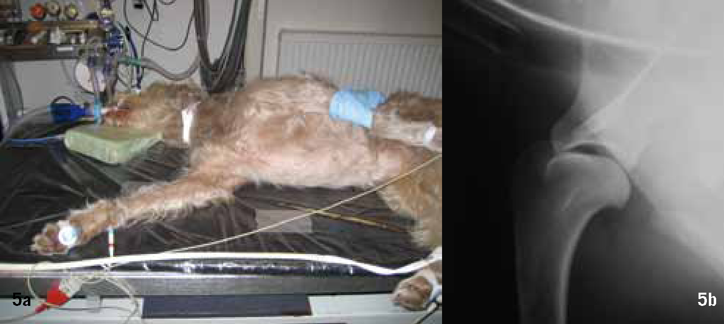
    A standard examination of the shoulder joint requires two views mediolateral (ML) and caudocranial (CdCr), where tendon or muscle involvement is suspected then the skyline view is taken. Where depth of tissue is >10 cm, the ML and CdCr views should be taken using a medium speed cassette and a grid (Potter Bucky if possible). If <10 cm then use a slow speed cassette on the table top. General anaesthesia or sedation is required.

    Shoulder joint — ML

  • With the animal in lateral recumbency, affected limb down, secure limb in cranial ventral traction using a tie.
  • Secure the contralateral limb caudally and dorsally, avoid over rotation.
  • Extend the head and neck dorsally to avoid superimposition of the trachea.
  • Centre on the scapular acromion (Figure 5a and b).
  • Figure 5a. Shoulder positioning mediolateral. b. Shoulder radiograph mediolateral.

    Shoulder joint — CdCr

  • With the animal supported in dorsal recumbency draw the limb cranially in full extension and secure with a tie. A foam wedge under the carpus may be required for support depending on the capabilities of the limb.
  • Feel for the cranial edge of the scapular body, this should be perpendicular to the table top. Ensure the forelimb is not abducted, which would open the shoulder joint.
  • Centre on the scapular acromion (Figure 6a and b).
  • Figure 6a. Shoulder positioning caudocranial. b. Shoulder radiograph caudocranial

    Shoulder joint — skyline (tangential)

  • With the animal in sternal recumbency raise the head and healthy limb, turning away from the midline.
  • The elbow and shoulder of the affected limb should be supported and held in maximum flexion while being kept parallel to the body.
  • Abduct the foot and carpus of the affected limb away from the area of interest.
  • Centre on the intertubercular (biceps) groove of the humerus (Figure 7a and b).
  • Figure 7a Shoulder positioning Skyline. b. Shoulder radiograph skyline.

    The elbow joint

    The elbow joint is complex and can be positioned in a number of ways to view all the structures radiographically. A slow film/screen combination should be used on the table top. General anaesthesia or sedation is required.

    The British Veterinary Association (BVA)/Kennel Club run the elbow dysplasia scheme and score the elbows based on two ML views:

  • Neutral ML — to look at congruency, the elbow is extended to 1100
  • Flexed ML — to assess the anconeal process, the elbow is flexed 450
  • It is important in each view to avoid rotation. Full procedure notes for the scheme can be downloaded from the BVA website.
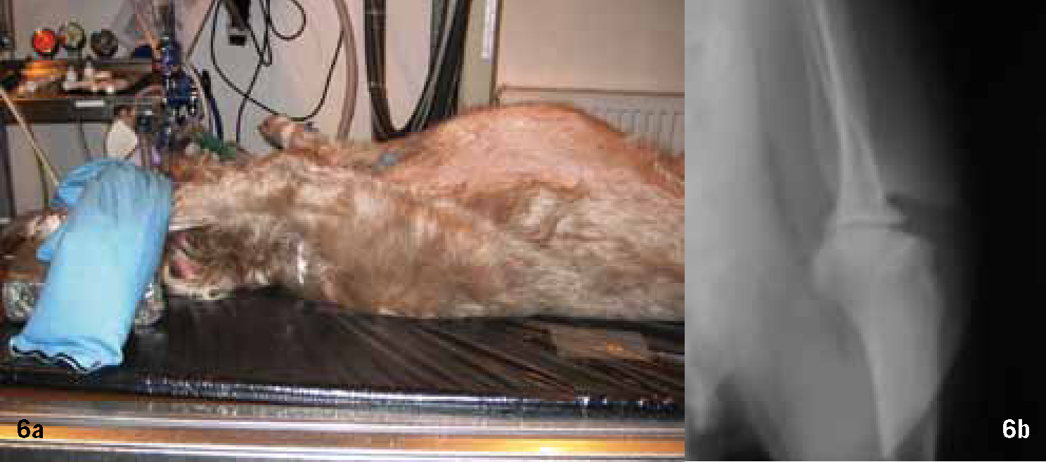
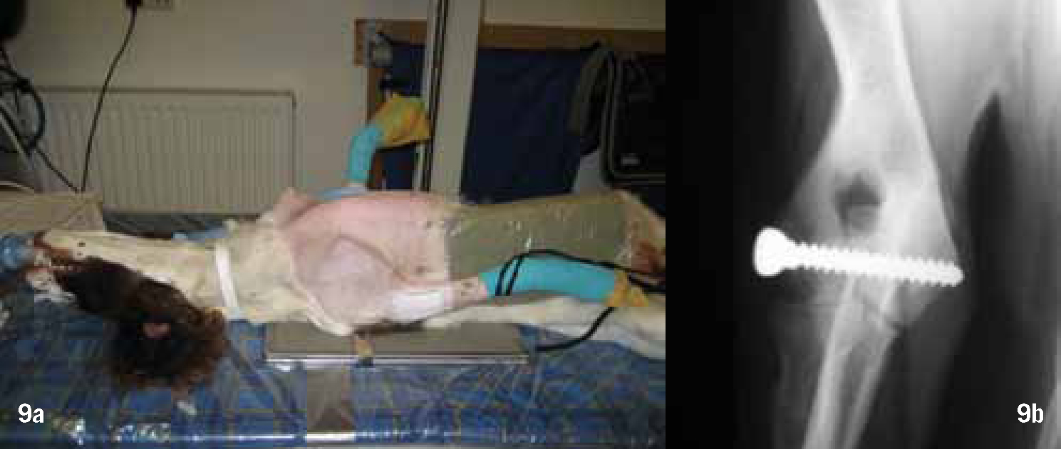
    Elbow joint — ML

  • With the animal in lateral recumbency, affected limb down, draw the contralateral limb dorsally and caudally avoiding rotation.
  • Position and secure the leg cranially to produce the required angle, a foam wedge under the carpus and sometimes the olecranon will be required to avoid rotation.
  • Extend the head and neck dorsally.
  • Centre on the epicondyle of the humerus (Figure 8a and b).
  • Figure 8a. Elbow positioning mediolateral. b. Elbow radiograph mediolateral.

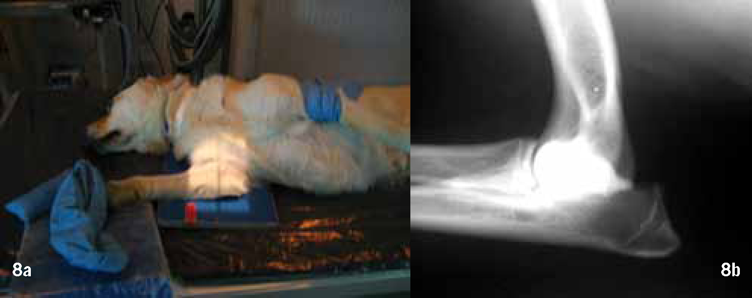
    Elbow joint — craniocaudal (CrCd)

    There are two ways of positioning for this radiographic view.

    Dorsal recumbency — This method is good for examining condylar fractures.

  • With the animal supported in dorsal recumbency extend the limb caudally and secure with sandbags or ties.
  • To keep the joint straight and avoid superimposition of the thoracic wall a foam wedge can be placed between the limb and body wall.
  • Centre midline of the humeral epicondyles (Figure 9a and b).
  • Figure 9a. Elbow positioning dorsal recumbency craniocaudal. b. Elbow radiograph dorsal recumbency craniocaudal post placement of trans-condylar screw following surgery for incomplete ossification of the humeral condyle.

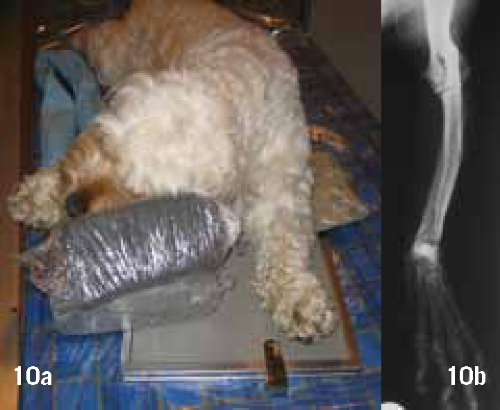
    Sternal recumbency — This method is useful when assessing deformities of the forelimb, especially in chondrodystrophic breeds, e.g. Basset hounds, the whole antebrachium should be included while still centring on the elbow.
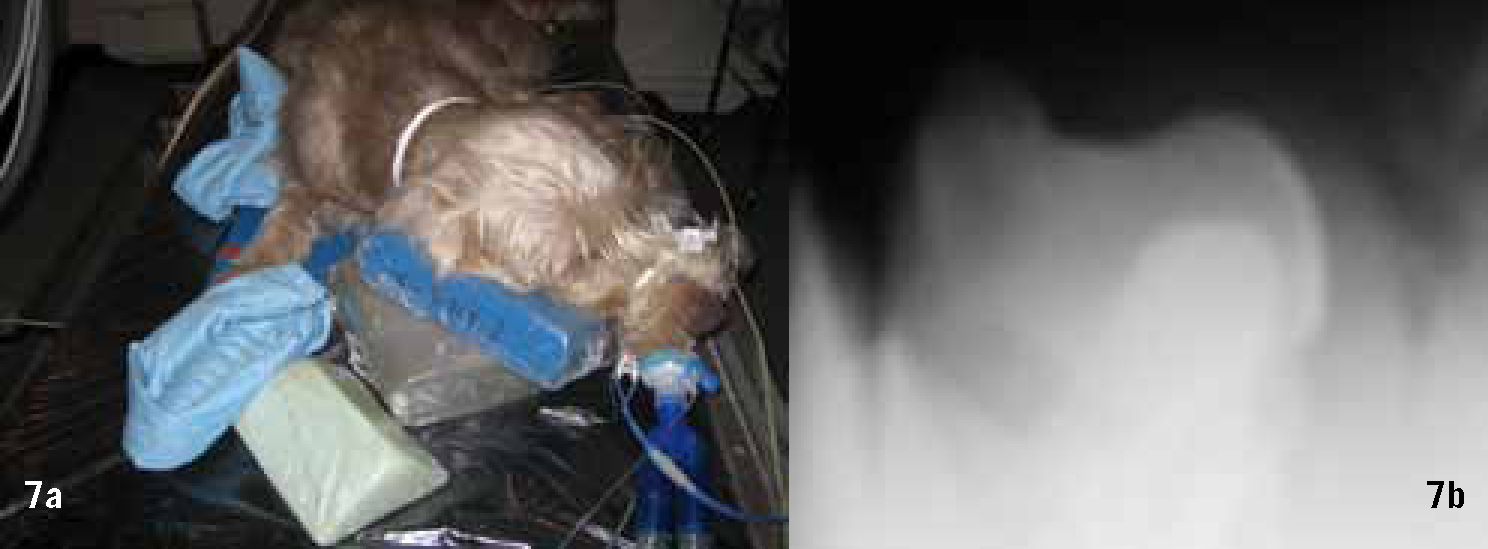
  • Place the animal in sternal recumbency.
  • Extend the affected limb cranially and support the elbow with a foam wedge.
  • Raise the contralateral forelimb and head with a foam pad to avoid rotation and superimposition.
  • Centre as above (Figure 10a and b).
  • Figure 10a Antebrachium positioning craniocaudal centring on the elbow. b. Antebrachium radiograph craniocaudal centring on the elbow showing limb deformity.

    Elbow joint — CdCr

    This view is often preferred by clinicians when suspecting problems with the medial coronoid process or osteochondrosis of the medial condyle of the humerus; however the increased object film distance (OFD) will mean that the image is magnified.

  • With the animal supported in dorsal recumbency draw the limb cranially in full extension avoiding rotation and secure with a tie, keep the elbow as close as possible to the table. Depending on the capabilities of the limb the carpus may need to be supported with a foam pad.
  • Centre as above.
  • The hips/pelvis

    The standard view used for assessment of the hips/pelvis is the VD extended view. The BVA/Kennel Club run a hip dysplasia screening scheme using this projection; full procedure notes for the scheme can be downloaded from the BVA website.

    A medium speed film/screen combination with a grid should be used except for very small dogs and cats where a slow film/screen combination is used on the table top. General anaesthesia or sedation is required.

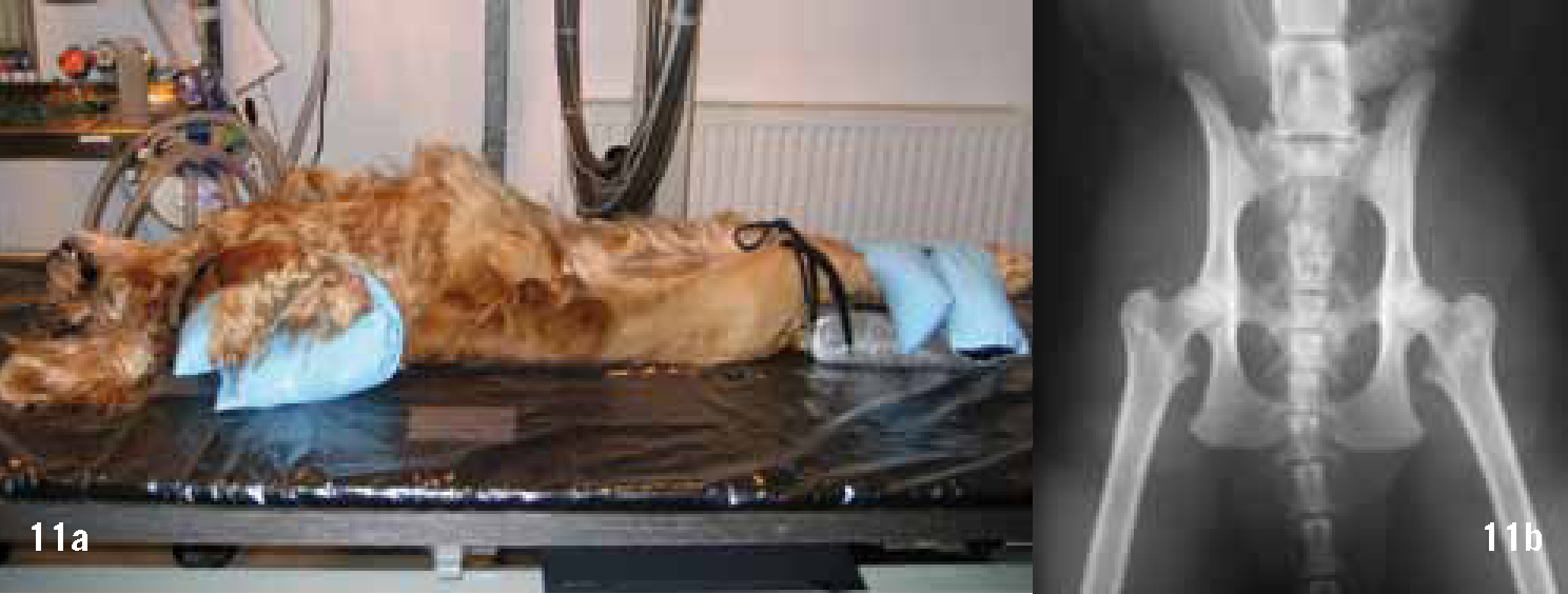
    Hips/pelvis — VD extended

  • Support the animal in dorsal recumbency avoiding longitudinal rotation.
  • Fully extend the legs, adduct and inwardly rotate so that the femora are parallel and secure, depending on the capabilities of the joint the limbs may need support with a foam pad under the hocks.
  • Ensure the tail is central.
  • Centre midline between the greater trochanters of the femur.
  • Tip — it is advisable to maintain the animal in position while the radiograph is processed so that adjustments can be made if axial rotation has occurred. To correct axial rotation raise the hip on the side on which the obturator foramen is smaller. Often ensuring that the head/neck end of the dog is straight will correct rotation at the pelvis (Figure 11a and b).

    Figure 11a Hips positioning ventrodorsal extended. b. Hips radiograph ventrodorsal extended, note this radiograph does not meet the requirements of the hip dysplasia scheme.

    The stifle joint

    The most commonly used projections for the stifle joint and associated structures are the ML and the CdCr. If cranial cruciate rupture is suspected then the hock is included. A slow film/screen cassette combination should be used on the table top. General anaesthesia or sedation is required.
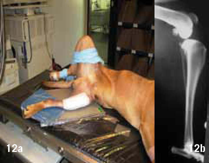
    Stifle joint — ML

  • With the animal in lateral recumbency, affected side down, abduct the contralateral limb so that it does not overlay the area of interest (see Tip).
  • The stifle should be allowed to rest on the cassette in a neutral position. To achieve the desired superimposition of the femoral condyles a foam wedge under the caudal aspect of the hock may be required.
  • Centre over the femoral condyles.
  • Tip — if the animal has well developed musculature on the hind limbs, e.g. Staffordshire Bull terriers, it may be easier to draw and secure the limb cranially or place a foam wedge under the hip (Figure 12a and b).

    Figure 12a Stifle positioning mediolateral including hock. b. Stifle radiograph mediolateral including hock.

    Stifle joint — CdCr

  • With the animal in sternal recumbency extend the affected limb caudally supporting the patella with a foam wedge.
  • Flex and raise the contralateral limb so that the trochlear groove of the affected limb is central. Avoid the tail obscuring the area of interest.
  • Centre on the distal part of the patella (Figure 13a and b).
  • Figure 13a Stifle positioning caudocranial including hock. b. Stifle positioning caudocranial including hock.

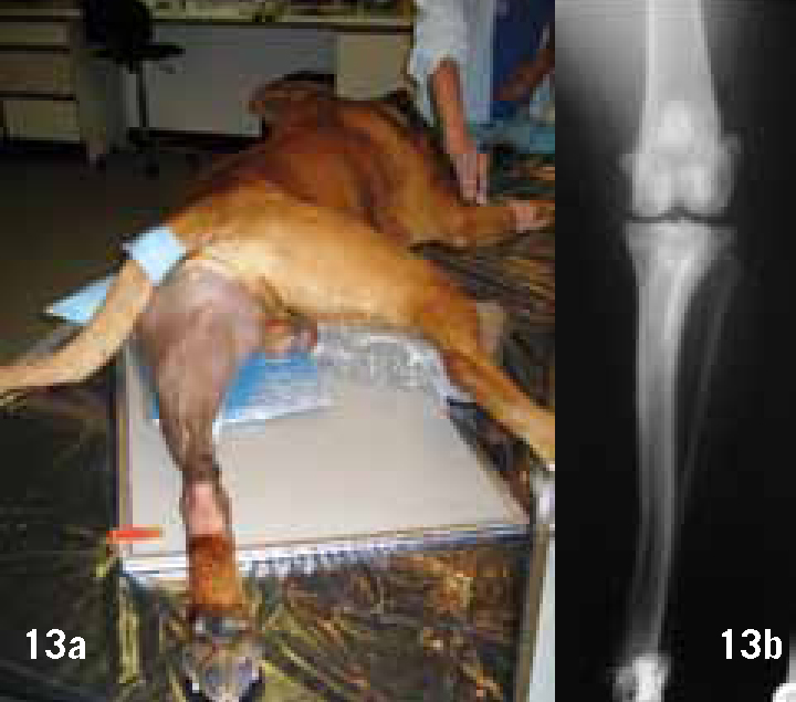
    Tip — Moving the tail to the side of the affected limb will aid positioning and avoid medial rotation.

    Conclusion

    The production of diagnostic orthopaedic radiographs is challenging, but using a standardized technique and following the basic principles outlined above can be very rewarding.

    Key Points

  • The results of a good radiographic examination can provide definitive information for diagnosis.
  • Manual restraint should always be avoided.
  • It is important to use a standard technique with good preparation.